2. CAN network basics
#What CAN is
CAN (Controller Area Network) is a communication network created in the 1980s to connect a vehicle's electronic modules with few wires. Instead of one wire per signal, all modules share a single pair of wires, the bus, and exchange short messages over it. The standard that defines the network is ISO 11898.
Three ideas explain almost everything about CAN:
- Everyone hears everything. When a module transmits, all the others receive the message. Each one decides whether that message matters to it or not.
- The message has a name, not a recipient. Each message carries an identifier (ID) that says what it contains, for example "engine speed and temperature". There is no destination address.
- There is no boss. Any module can start transmitting when the bus is free. If two start together, the network itself decides which one continues, without losing time and without corrupting the message (see Arbitration, below).
In practice, the VCU uses CAN to talk to FuelTech devices (O2 sensor, ignition module, injector drivers, dashes), to third-party equipment and to the vehicle's original modules.
#Physical layer: the wires
The high-speed CAN bus uses two wires, CAN_H (CAN high) and CAN_L (CAN low), twisted together. The information is in the voltage difference between them, not in the voltage of each one relative to ground. That is why the network tolerates the engine's electrical noise well: interference that enters both wires at the same time does not change the difference.
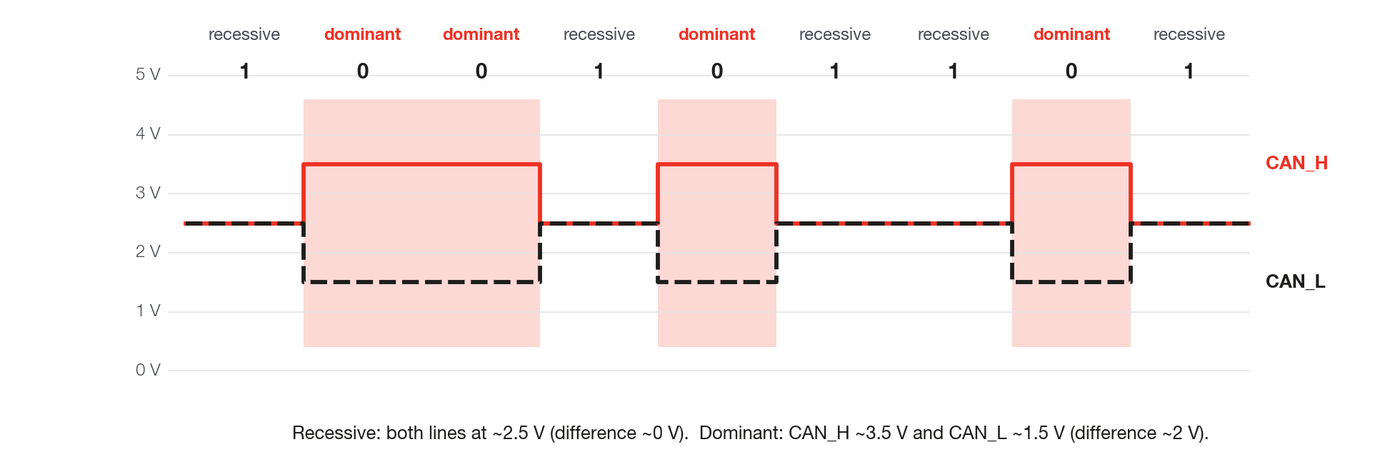
The two possible states are:
- Recessive (bit 1): both wires sit at about 2.5 V. Nobody is driving the bus.
- Dominant (bit 0): CAN_H rises to about 3.5 V and CAN_L drops to about 1.5 V, a difference of about 2 V.
If one module transmits dominant and another recessive at the same instant, the bus becomes dominant. This simple rule is the basis of arbitration and of acknowledgment.
#Topology and termination
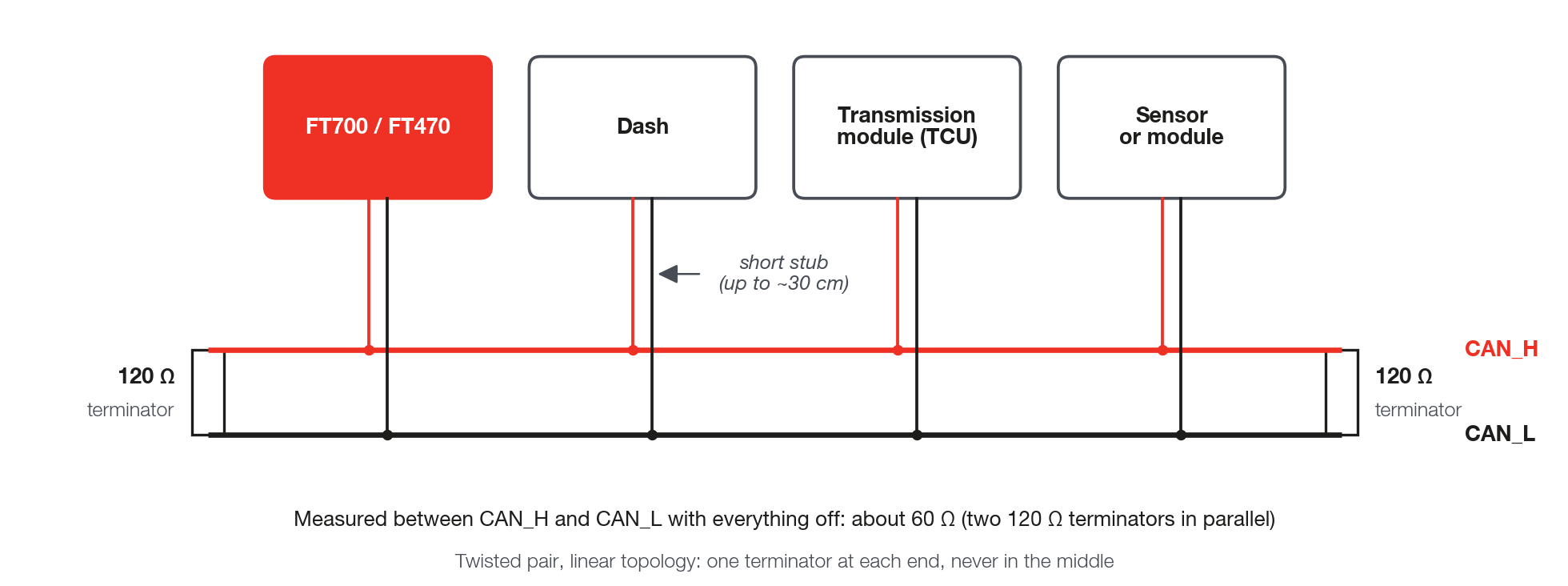
The bus is a line, with a beginning and an end. Each module connects to it through a short stub. At the two ends of the line, and only there, a 120 Ω resistor goes between CAN_H and CAN_L, called a terminator. It absorbs the signal that reaches the end of the wire and keeps it from bouncing back and mixing with the next bits.
Practical installation rules:
- Use twisted pair (about 1 twist every 2 to 3 cm, roughly 1 in). Shielded cable helps in installations with a lot of noise; ground the shield at one end only.
- Build it as a line. Avoid star topology, with several long branches leaving the same point.
- Keep stubs short, preferably up to 30 cm (about 12 in).
- Exactly two terminators per bus. Many modules already have an internal terminator; others, such as the VCU, let you turn the terminator on or off in the software.
The total length of the network limits the speed, because the signal has to go and return within one bit. The values below are usual cable references for high-speed CAN:
| Bit rate | Reference maximum length |
|---|---|
| 1 Mbit/s | 40 m (about 130 ft) |
| 500 kbit/s | 100 m (about 330 ft) |
| 250 kbit/s | 250 m (about 820 ft) |
| 125 kbit/s | 500 m (about 1,640 ft) |
In a race car the distances are short and any of these rates usually works. What usually fails is wrong termination, a poorly made splice and a long stub.
#The CAN frame
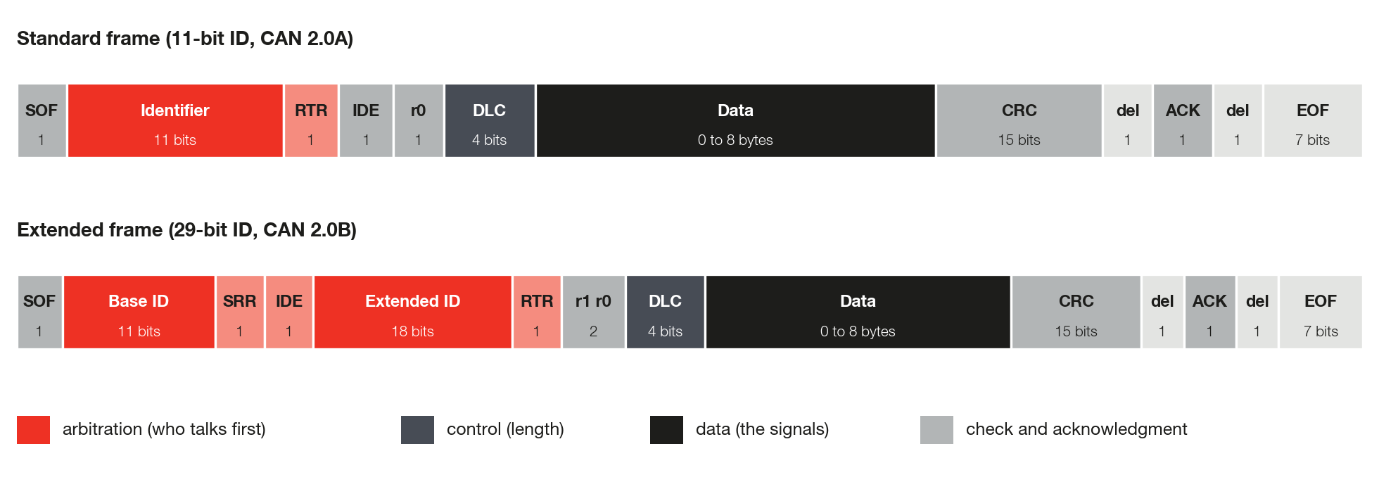
Each message travels inside a frame. The frame has fixed fields before and after the data: they identify the message, say how many bytes it has and check whether it arrived without error.
| Field | What it does |
|---|---|
| SOF | Start of Frame. A dominant bit that synchronizes all modules. |
| Identifier (ID) | The name of the message and, at the same time, its priority. It has 11 bits in the standard frame (0x000 to 0x7FF) or 29 bits in the extended frame (up to 0x1FFFFFFF). |
| RTR, IDE, SRR | Control bits: they say whether the ID is standard or extended and whether the frame is a data frame or a remote request (rare today). |
| DLC | Data Length Code: the number of data bytes, from 0 to 8 in classic CAN. |
| Data | From 0 to 8 bytes. This is where the signals (engine speed, temperature, pressure...) are. |
| CRC | Check code calculated over the frame. The receiver recalculates it and compares. |
| ACK | Acknowledgment. Any module that received the frame without error forces this bit to dominant. |
| EOF | End of Frame. |
IDs are usually written in hexadecimal, with the 0x prefix. ID 0x640, for example, is 1600 in decimal. DBC files write the ID in decimal; screens and analyzers usually use hexadecimal.
#Arbitration: who talks first
When the bus becomes free, any module can start transmitting. If two start at the same time, each one keeps sending its ID bit by bit and, at the same time, reading the bus. Since the dominant bit (0) wins over the recessive bit (1), the module that sends 1 and reads 0 realizes it lost, stops transmitting and starts listening. The winner does not even notice the contest: its frame continues intact.
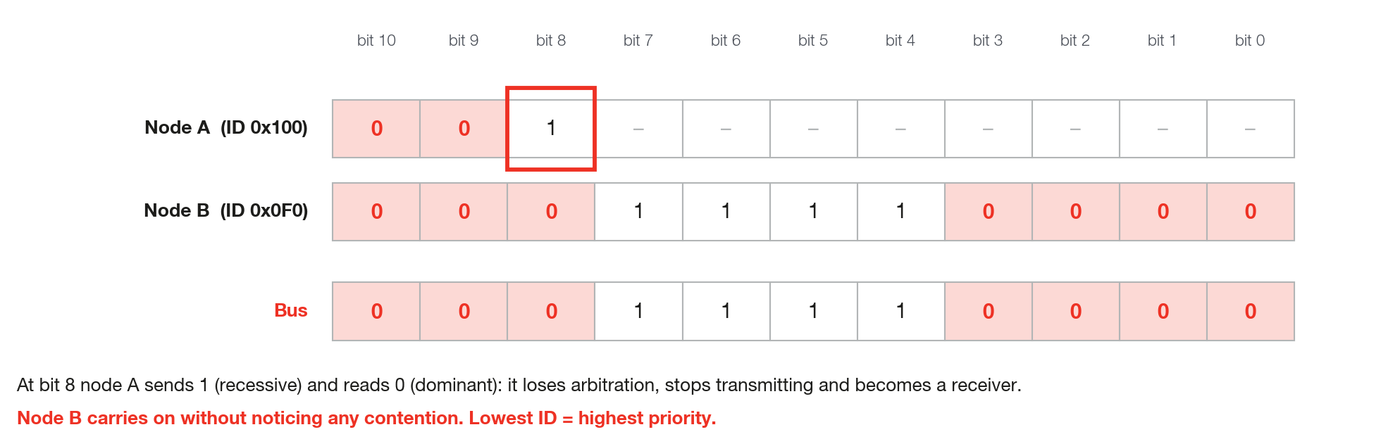
The practical consequence is that a lower ID has higher priority. Critical messages, such as engine speed and torque, usually have low IDs. A module that transmits a very low ID very often can delay all the others.
#Bit rate and sample point
All modules on a bus must use the same bit rate (baud rate; on the CAN ports screen, Baudrate, in kbps, the same as kbit/s). The most common rates in vehicles are 500 kbit/s and 250 kbit/s; racing equipment and the FuelTech FTCAN network use 1 Mbit/s. A module at a different rate understands nothing and, worse, generates errors that disturb the others.
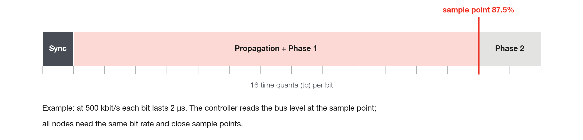
Each bit is divided into small time slices. The sample point is the instant, within each bit, when the controller reads whether the bus is at 0 or 1. It is given as a percentage of the bit duration and normally sits between 75% and 87.5%. Modules with very different sample points may even work on the bench and fail with a long cable or with noise.
#Error detection
CAN is a very robust network because all modules watch all frames. The main mechanisms are:
- CRC: the receiver recalculates the check code; if it does not match, the frame is discarded.
- Acknowledgment (ACK): the transmitter waits for at least one other module to confirm reception. By the standard, a module alone on the bus never receives acknowledgment and keeps repeating the frame (the VCU's reaction is in chapter 7).
- Bit stuffing: after five identical bits in a row, the transmitter inserts an inverted bit. Six identical bits in a row indicate an error.
- Form check and bit monitoring: fixed fields with a wrong value, or a bit that does not come out as transmitted, are also errors.
When it detects an error, the module destroys the frame with an error signal and the transmitter tries again. Each module keeps error counters. With few errors it works normally; with too many it goes into a restricted (error-passive) state and, at the limit, disconnects from the bus so it does not disturb the others. This state is called bus-off. A different bit rate, wrong termination and CAN_H swapped with CAN_L are the most common causes of a module in bus-off.