10. Customizable CAN
#Purpose
Customizable CAN builds and interprets CAN frames defined by you. It is the tool for talking to equipment that does not use the FTCAN protocol: dashes and dataloggers from other brands, transmission modules, third-party injection or ignition modules, CAN sensors and the vehicle's original modules (see the limits at the end of this chapter).
With it the VCU can:
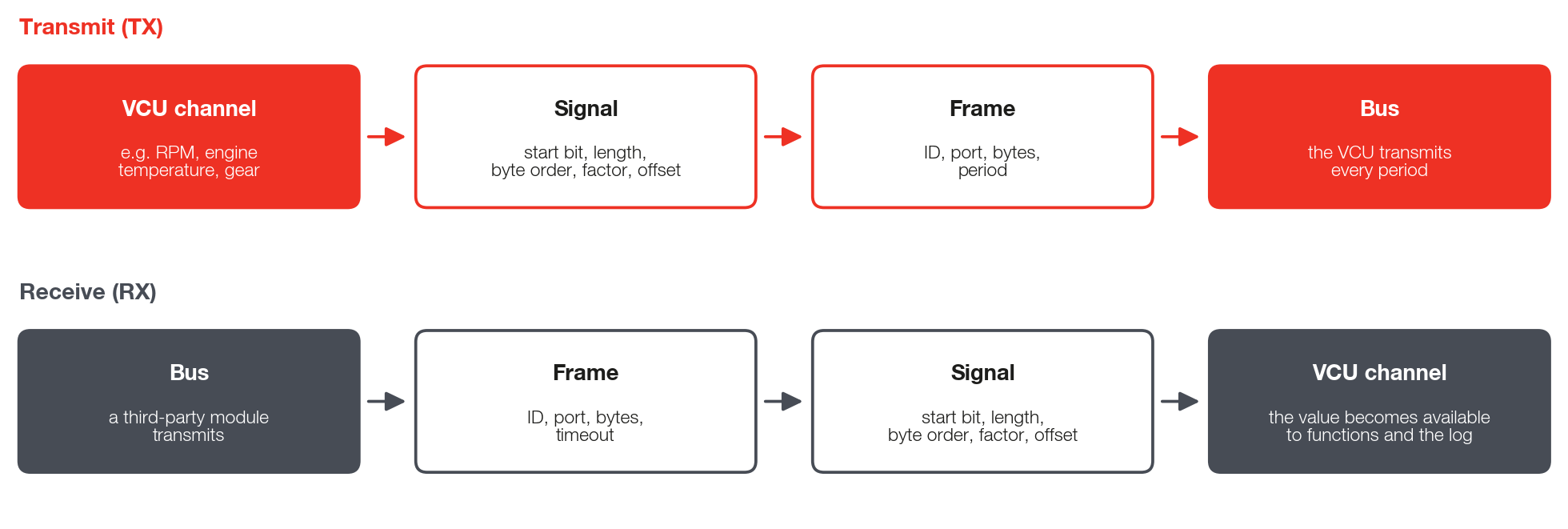
- Transmit (TX): take data from the VCU (engine speed, temperature, gear, pressures...) and send it in frames with the ID, bit position and scale that the other equipment expects.
- Receive (RX): listen for an ID, extract the signals from the frame and write the values to VCU channels, which then exist like the other channels.
The path is VCU settings > Customizable CAN, right below CAN ports. The function is disabled by default: turn it on before configuring. Customizable CAN works on a port configured in RAW mode or in FTCAN 2.0; for third-party equipment use RAW mode, at the equipment's rate. Check in CAN ports whether the chosen port is on: the editor does not do this check. Before transmitting on a vehicle's original network, reread the warning in the Presentation.
#Frames and signals
The screen has two tabs:
- Signals: the signal bank, with up to 48 signals. Each signal links a VCU channel to a bit position (start bit, length, order, scale and offset).
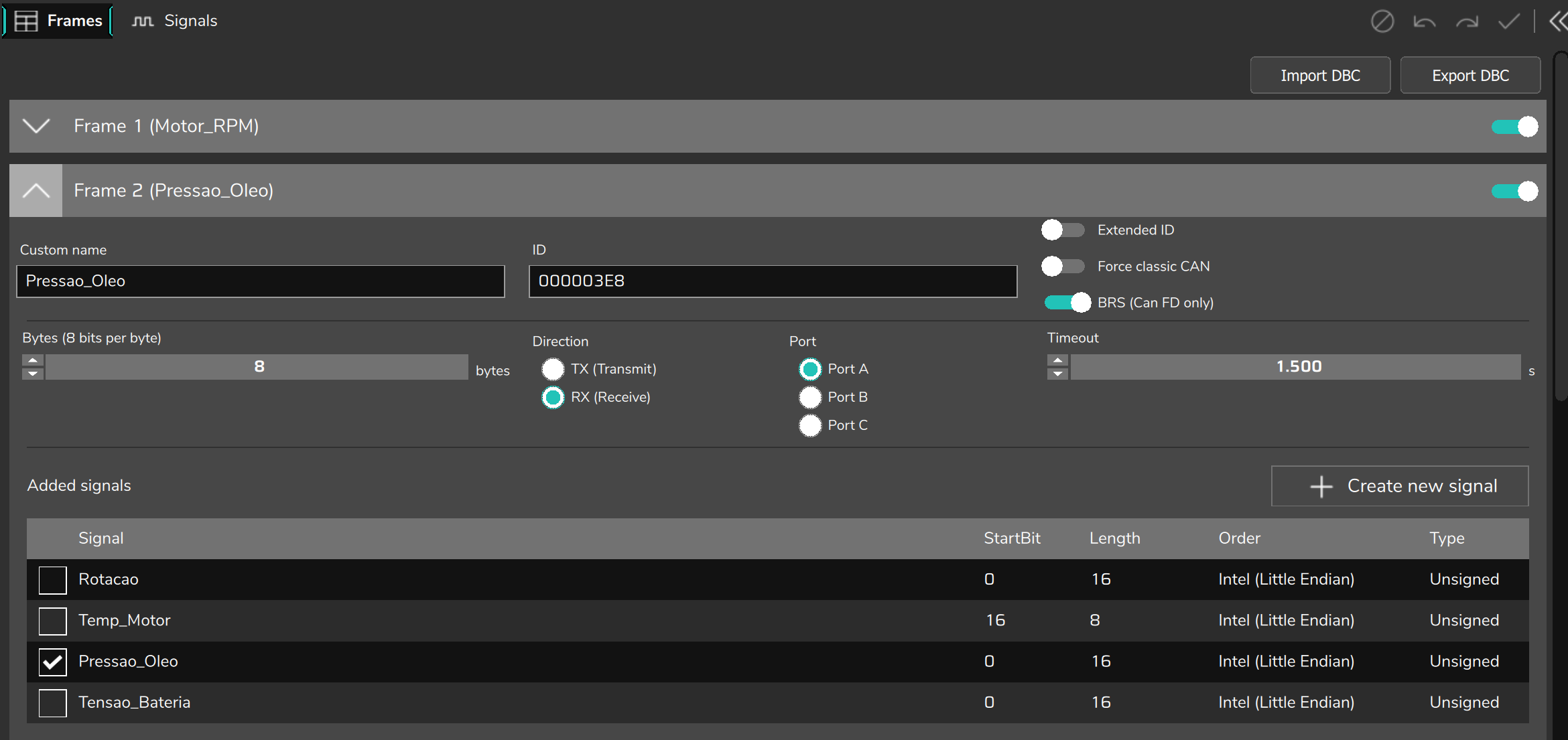
- Frames: 16 fixed frames (Frame 1 to Frame 16). Each frame has an ID, port, size, direction, time and the list of signals that make it up.
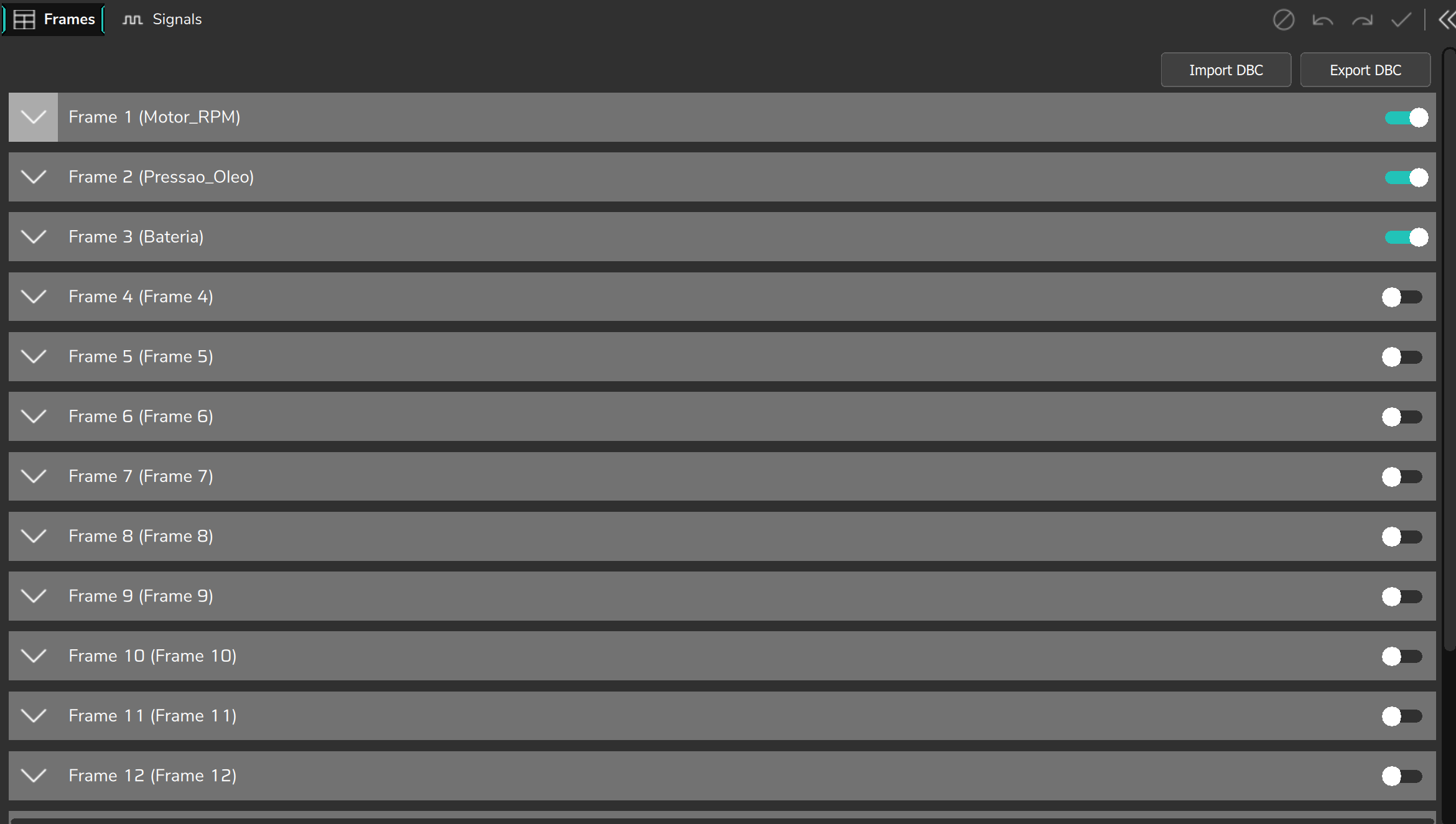
A signal is defined once and then selected, by checking its box, in each frame it belongs to. The same signal can be selected in more than one frame; in that case it takes the same bit position in all of them.
| Feature | Limit |
|---|---|
| Frames | 16 |
| Signals in the bank (a signal checked in several frames counts once) | 48 |
| Frame size | 1 to 8 bytes; up to 64 bytes on a port with FD mode |
| Signal size | 1 to 32 bits |
| Start bit | 0 to 511 |
| Ports | A, B and C |
#Frame fields
Each frame has an Enabled switch in its header. With it off, the frame is grayed out and the VCU ignores it.
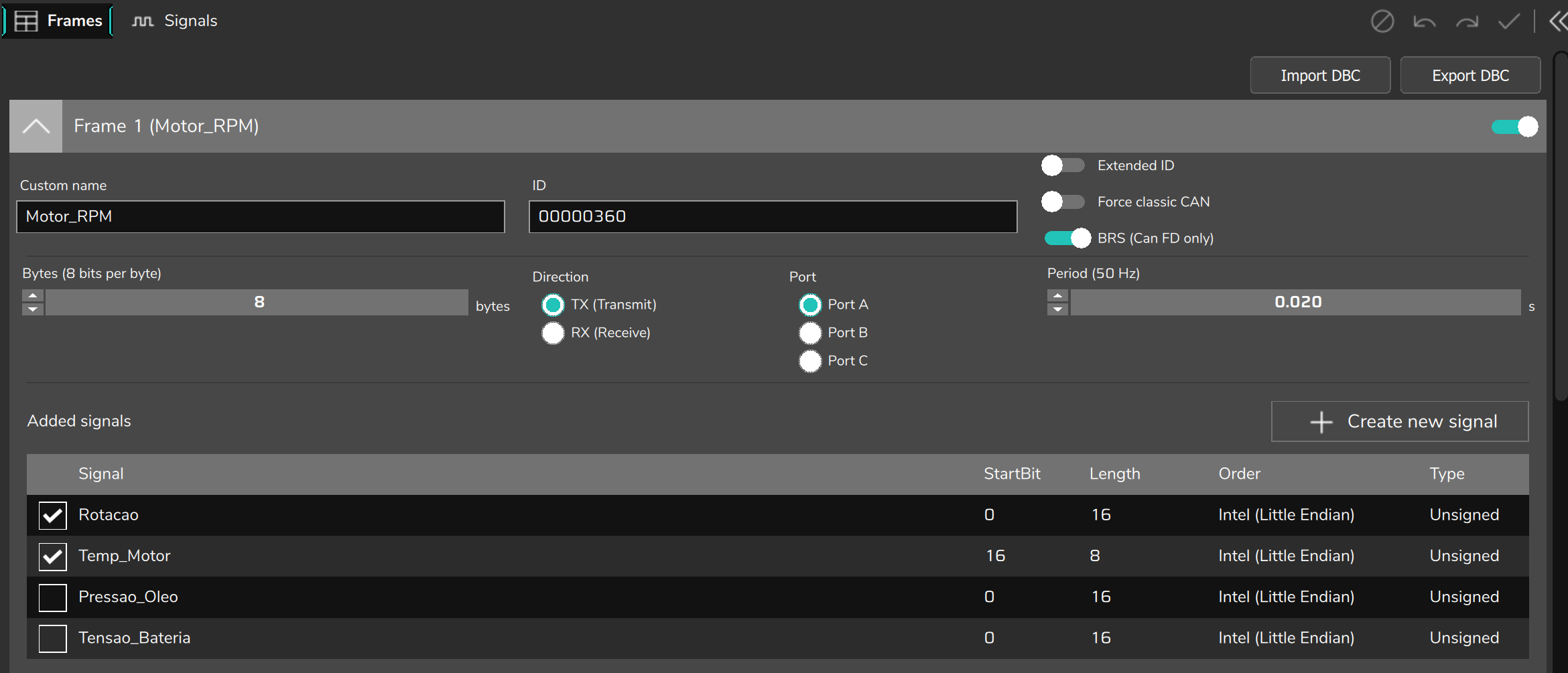
| Field | What it does |
|---|---|
| Custom name | Name of the frame in the editor and in the exported DBC. It does not go to the VCU. |
| ID | Identifier in hexadecimal. Up to 7FF with a standard ID; up to 1FFFFFFF with Extended ID. The editor does not accept the same ID in two frames, even on different ports or directions. |
| Extended ID | On: 29-bit ID (extended). Off: 11-bit ID. It is on by default in a new frame: confirm what the equipment uses. |
| Bytes | Size of the data. Up to 8 on a port without FD mode; up to 64 on a port with FD mode. |
| Direction | TX (Transmit): the VCU sends the frame every Period. RX (Receive): the VCU listens for the ID and decodes the signals. |
| Port | Port A, B or C, the same letter as on the CAN ports screen. The FT470 has only Ports A and B: option C does not apply to it. |
| Period (TX) | Interval between transmissions, from 0.01 s (100 Hz) to 60 s. The field title shows the equivalent frequency. |
| Timeout (RX) | Maximum time without receiving the frame, from 0.5 to 60 s. When it expires, the frame's signals go to zero and are marked as having no valid data. |
| Force classic CAN | Only on a port with FD mode. Sends this frame as classic CAN, without BRS, for equipment that does not understand CAN FD. Use at most 8 bytes in this frame: the editor does not limit this by itself. |
| BRS (Can FD only) | Only on a port with FD mode. When on, the data part goes at the port's FD data rate. |
| Added signals | The list of the 48 signals with a checkbox. Check the boxes of the ones that make up this frame. |
#Signal fields
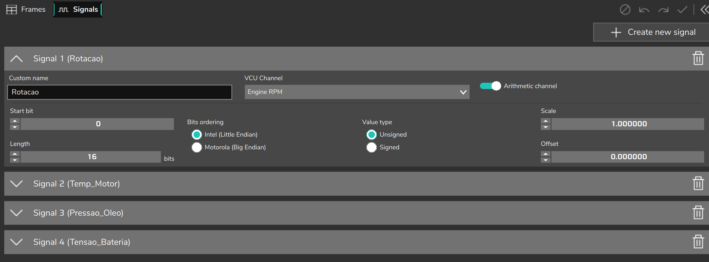
| Field | What it does |
|---|---|
| Custom name | Name of the signal in the editor and in the exported DBC. It does not go to the VCU. |
| VCU Channel | The data the signal carries. In a TX frame it is the source of the value; in an RX frame it is the channel where the received value is written. With None, the signal carries a Fixed value. |
| Arithmetic channel | Defines how the VCU does the calculation between the channel and the bits (see below). It is on by default. When off, the calculation uses only positive integers. |
| Start bit | Position of the signal in the frame (the start bit). In Intel it is the least significant bit; in Motorola it is the most significant, in the DBC numbering. |
| Length | Number of bits of the signal, from 1 to 32. |
| Bits ordering | The byte order from chapter 3: Intel (Little Endian) or Motorola (Big Endian). A new signal is created as Motorola. |
| Value type | Unsigned or Signed (two's complement, see chapter 3). Applies to reading RX frames. |
| Scale and Offset | The signal's factor and offset: value = raw × Scale + Offset. |
| Fixed value | Only with VCU Channel set to None. Value in hexadecimal (up to 8 digits) written directly into the signal's bits, without scale. |
#Arithmetic channel
This field needs attention when you enter the signal manually.
- On (recommended): the VCU does the calculation with real numbers. When transmitting: raw = (value − Offset) ÷ Scale. When receiving: value = raw × Scale + Offset. It works with a fractional scale (0.1; 0.125; 0.01...) and with a negative offset (−40, −500...).
- Off: the calculation is done only with positive integers. The fractional part of the channel is discarded and Scale and Offset also become positive integers. A scale of 0.1 becomes 0 and an offset of −40 stops working.
#How the VCU builds the bits
A few rules help you predict exactly what goes onto the network:
- Truncation, not rounding. When transmitting, the VCU cuts off the fractional part of the raw value. A temperature of 92.5 °C with scale 1 and offset −40 is sent as 132 (92 °C). If resolution matters and the receiving equipment lets you choose the scale, use a smaller one (for example 0.1) and set the same one on both sides.
- No saturation. If the value does not fit in the signal size, only the lowest bits are written and the number wraps around. An 8-bit unsigned signal with offset −40 covers −40 to 215 °C; 250 °C would come out as a low value. Size the length for the real range.
- Free bits go out as zero. Bits in the frame that do not belong to any signal are transmitted as 0.
- The value is read at the moment the frame is built.
- An overlapping signal or one outside the frame disables the frame. If two signals checked in the same frame use the same bit, or if a signal goes past the last byte, the VCU disables the frame and reports an error. Check the positions before writing: the editor does not draw the bit map.
#Receiving (RX): important rules
- The VCU compares the exact ID. There is no range or ID mask.
- Bytes is the minimum accepted size. A frame that arrives with fewer bytes than configured is ignored. A larger frame is accepted. If in doubt, check the real size with the sniffer.
- Timeout: if the frame stops arriving, after the Timeout the frame's channels go to zero and are marked as having no valid data. The value returns as soon as a new frame arrives. The check is done in steps of 0.1 s; use a Timeout of at least three times the period at which the equipment transmits, and never less than 0.5 s, the field's minimum.
- Destination channel: prefer the channels Custom measurement #01 to Custom measurement #36: they are free user inputs and can be renamed. Writing to a channel the VCU itself calculates (engine speed, MAP, temperature of a sensor connected to the VCU) is not recommended: the received value tends to be overwritten by the real measurement.
- Avoid using, on the same port, an ID that another function already listens for (Steering wheel, Racelink, External TCU, custom packages): only one of them receives the frame.
#Transmitting (TX): important rules
- The minimum Period is 0.01 s (100 Hz).
- Frames are sent in numeric order. With many frames at short periods, the higher-numbered ones can go out with some delay relative to the configured period. Give the fastest frames the lowest numbers (Frame 1, 2, 3...).
- To transmit, another module must be connected on the bus to acknowledge the frames. Alone on the bus, the VCU drops the frame 20 to 30 ms after sending it and, after three failures in a row, stops transmitting on the port for 1.5 s before trying again.
#Errors and how to see them
The VCU indicates a problem in Customizable CAN in three ways:
- "Custom CAN: Frame error" channel: each bit of the value corresponds to one frame (bit 0 = Frame 1, bit 1 = Frame 2...). Value 0 = no frame with an error. It appears in the VCU channel list. In channel and notification names, the app writes "Custom CAN" for Customizable CAN.
- "Custom CAN: Frame (de)composition error" notification: appears when a frame was disabled by an error. It is only shown about 60 s after the map is written (the equivalent notification for custom packages comes out in about 15 s).
- Map validation in FuelTech Vision (the Configuration alert validation window): warns about a frame with more than 8 bytes on a port without FD mode and a signal with Arithmetic channel off and a fractional scale or negative offset.
Situations that disable the frame or cause it to be ignored:
- Frame enabled with no signal checked.
- Period (in a TX frame) or Timeout (in an RX frame) out of range.
- TX frame with an ID greater than 7FF and Extended ID off.
- Overlapping signals, a signal beyond the frame size or an invalid channel.
- When receiving, a signal beyond the size of the frame that arrived.
#Customizable CAN limits
In version 3.0 Customizable CAN does not generate a checksum (a check value calculated over the data) or a rolling counter (a value that changes with every frame). It does not handle multiplexed signals (signals whose meaning depends on a selector in the frame itself). It transmits only periodically, not on event, and does not send or answer remote frames. There is no timeout per signal, only per frame. It does not work with IEEE floating-point values (numbers with decimal places) or with signals longer than 32 bits. A modern original (OEM) module that requires a checksum or counter may reject these commands.