2. How the pump delivers fuel
#The lobe and the stroke
The high pressure pump is driven by the camshaft.
The camshaft has lobes for the pump. Each lobe pushes the plunger once per engine cycle.
Each pass of a lobe is one pump stroke: one delivery of fuel to the rail.
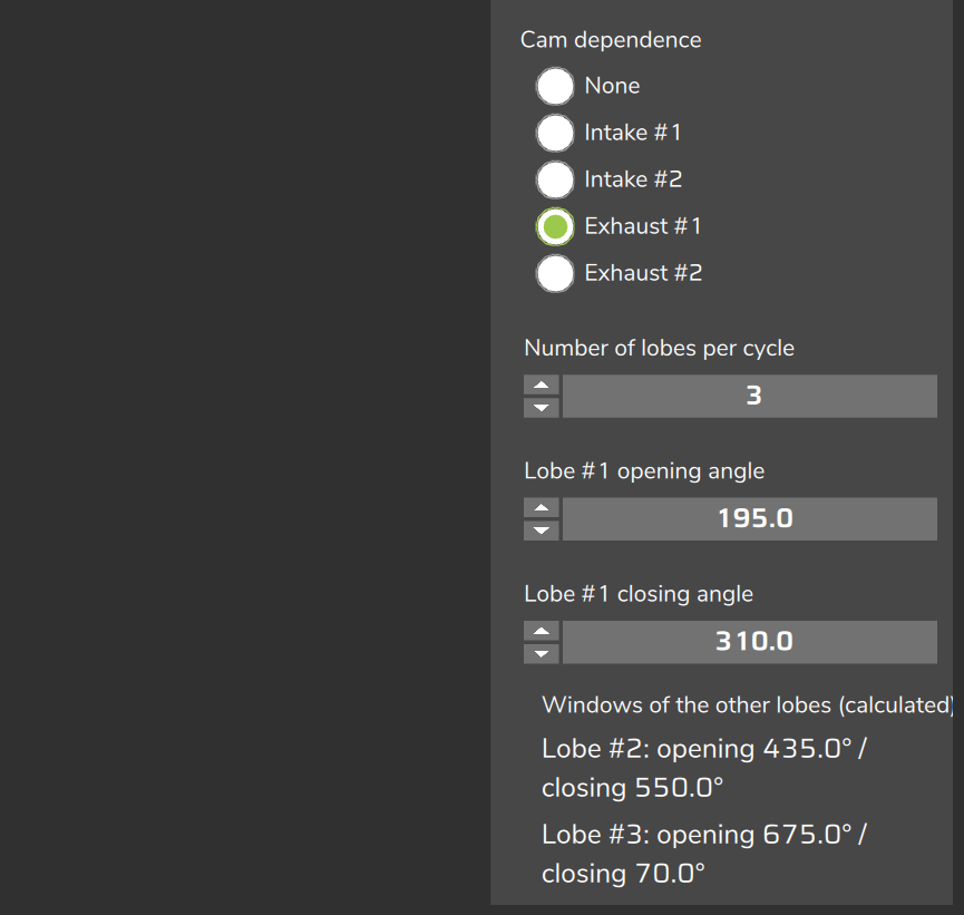
The Number of lobes per cycle field tells how many lobes (strokes) the pump has per cycle.
The VCU sends one pulse for each lobe.
On one rail, the number of strokes per second is:
strokes per second = rpm × lobes ÷ 120Example: at 6000 rpm, with 3 lobes, that is 150 strokes per second.
The pressure loop uses the sensor reading filtered at the stroke frequency. See Closed loop and PID.
#The valve and the pulse
The pulse is the interval in which the VCU tells the pump to deliver fuel to the rail.
The Output behavior field tells how the pulse appears on the VCU output:
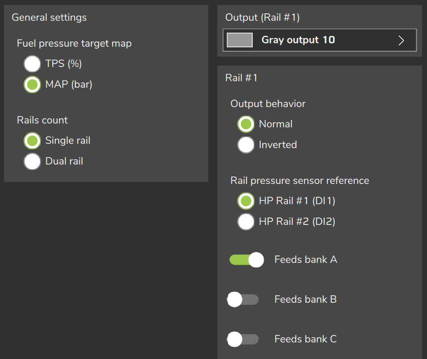
- Normal: the pump delivers with the valve energized. The output is off at rest and the pulse turns it on.
- Inverted: the pump delivers with the valve off. The output is energized at rest and the pulse turns it off.
Only the electrical polarity changes. The pulse time is the same in both.
Choose according to your valve: if it delivers energized, Normal. If it delivers de-energized, Inverted.
To check the polarity on the engine, see Commissioning and tuning step by step.
#Crankshaft degrees and camshaft degrees
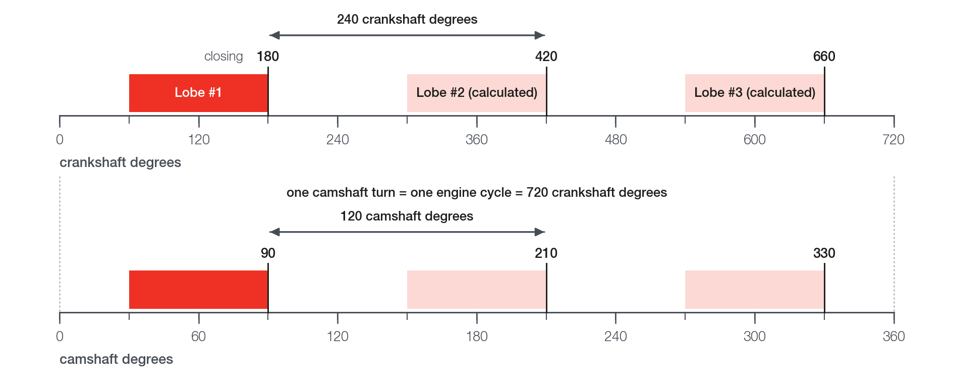
The cycle of a four-stroke engine has 720 crankshaft degrees.
The camshaft makes one turn in that cycle: 360 camshaft degrees.
One camshaft degree equals two crankshaft degrees.
The lobe fields on the screen are always crankshaft degrees, from 0 to 720, counted from TDC of cylinder 1 (top dead center: the piston of cylinder 1 at its highest point), the same zero as the injection and ignition angles.
The screen does not show the unit.
It is the same reference as the injection and ignition angles.
The lobes are evenly spaced in the cycle. With 3 lobes:
360 ÷ 3 = 120 camshaft degrees between lobes
720 ÷ 3 = 240 crankshaft degrees between lobes
"3 lobes = 120 degrees" is measured in camshaft degrees. In crankshaft degrees, which is what the screen uses, it is 240.
If your reference is in camshaft degrees, multiply by 2 before entering it; a position also has to be counted from TDC of cylinder 1.
The spacing for 1, 2 and 4 lobes and the windows of the other lobes are in The lobe angles.
#From time to angle
The VCU calculates the pulse in milliseconds and places it in crankshaft degrees:
crankshaft degrees = 0.006 × rpm × time in msExample: at 3000 rpm, 1 ms is 18 crankshaft degrees. At 6000 rpm, 1 ms is 36 crankshaft degrees.
The same pulse in milliseconds covers more crankshaft degrees as rpm rises.
#Where the pulse starts and where it ends
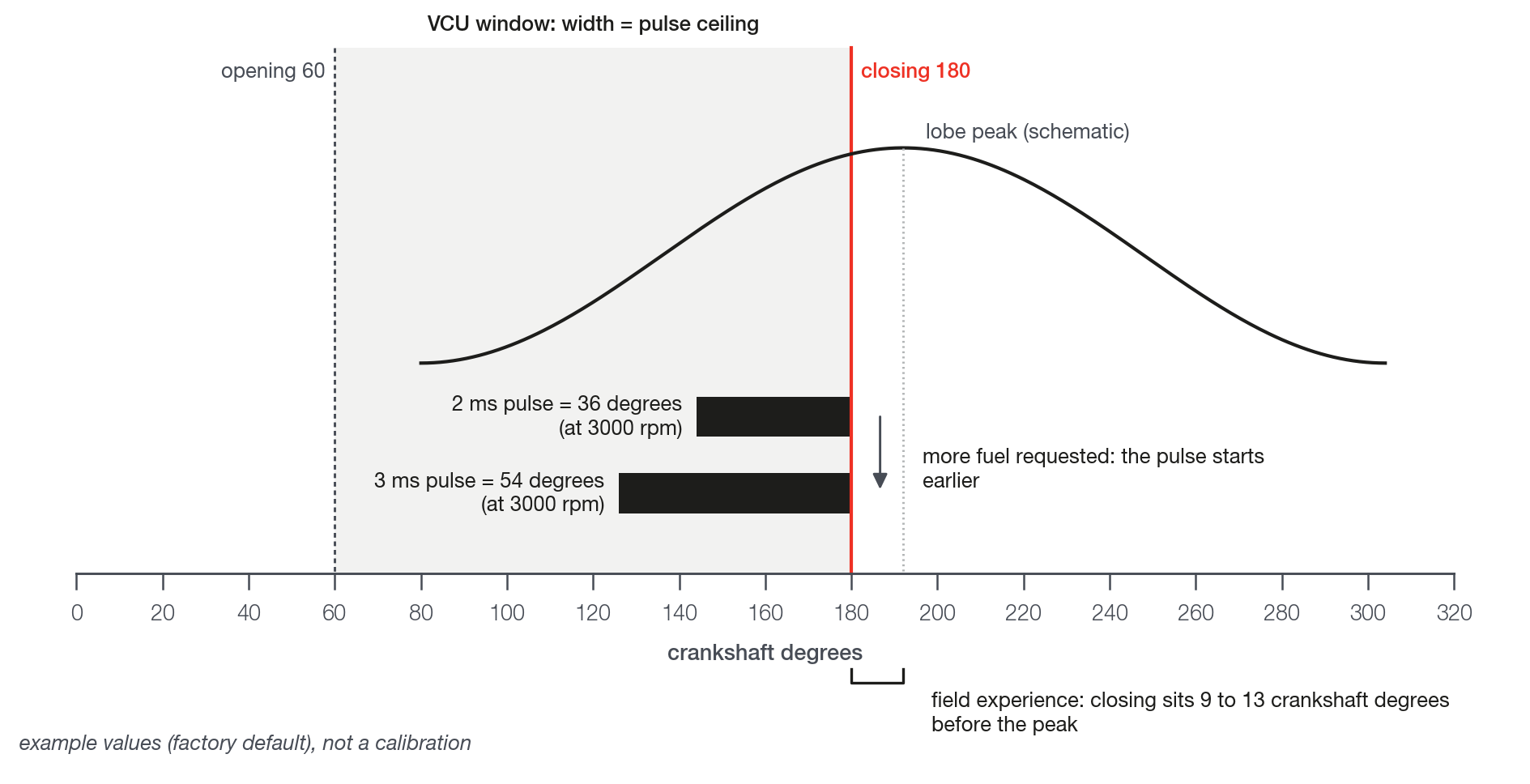
The Lobe #1 closing angle is where the pulse ends, with the exceptions listed below.
It is the phase reference of the pump.
The start of the pulse is the end minus the pulse duration, in crankshaft degrees.
The more fuel the rail asks for, the longer the pulse and the earlier it starts. The end does not change.
Example with the factory default (closing 180 crankshaft degrees, opening 60 crankshaft degrees, Valve delay (phase advance) at 0 and Cam dependence at None), at 3000 rpm:
- A 2 ms pulse covers 36 crankshaft degrees and starts at 144 crankshaft degrees.
- A 3 ms pulse covers 54 crankshaft degrees and starts at 126 crankshaft degrees.
- In both, the pulse ends at 180 crankshaft degrees.
The Lobe #1 opening angle is the earliest start the pulse can have.
The difference between closing and opening is the window width. The width is the ceiling of the pulse duration.
Opening and closing are the edges of the VCU command window. They are not the opening and closing events of the valve itself.
All lobes of a rail receive the same pulse. Only the position changes, from one lobe to the next.
Part of the pulse is the valve dead time and does not deliver volume. See Feed-forward (physical model) and trim.
The end of the pulse at the closing has exceptions:
- With Valve delay (phase advance) greater than zero, the whole pulse comes before the closing you entered. It only applies with feed-forward on. See The lobe angles.
- With Cam dependence different from None, the whole window follows the cam deviation, up to 90 crankshaft degrees. See The lobe angles.
- At cranking, with feed-forward on, the valve is held on directly, without following the closing. See Cranking and protections.
#What the log shows
The GDI - Rail 1 window: effective closing channel shows where the pulse ends, with the Valve delay (phase advance) and the cam deviation already applied.
The GDI - Rail 1 window: effective opening channel shows where the pulse starts. It is not the value of the opening field.
With the rail off or during cranking, both channels read 0.
The other pump channels are in Reading the log.
#Where the closing sits relative to the peak
The lobe peak is the point of highest lobe lift. It is the pump TDC.
Do not confuse the two TDCs. The zero of the fields is TDC of cylinder 1. The pump lobe peak is another point, at another angle.
The VCU does not know the lobe. It places the pulse by its end, at the closing angle you enter.
That is why the closing is the angle you calibrate.
The start of the pulse adjusts itself to the demand.
The closing sits near the lobe peak. It is not the exact peak.
The closing is the calibrated angle. It is not a measurement of the camshaft.
#Field experience
The sweep moves the opening and the closing together, at a fixed operating point, and looks for the angle at which the smallest pulse (in ms) holds the pressure target.
With the sweep, the closing usually ends up 9 to 13 crankshaft degrees before the peak.
The lobe peak comes from outside FuelTech Vision: from the camshaft card, from the pump manufacturer data or from an estimate.
The final closing is found by the sweep. The step-by-step procedure is in The lobe angles.