6. Closed loop and PID
The closed loop compares the target with the pressure measured in the rail and corrects the pump valve pulse.
This chapter explains the error, the Kp, Ki and Kd gains, the limits of the correction and the difference between the two ways of using the PID.
The target is in Pressure target.
The pulse calculated by the physical model is in Feed-forward (physical model) and trim.
#Two modes: PID as trim or PID only
The Enable feedforward (PID as trim) box defines the role of the PID.
On the PC it is on the PID settings page, in the Feedforward (physical model) group. It is off on a new map.
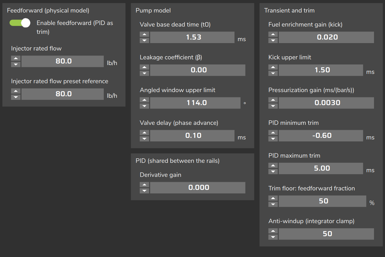
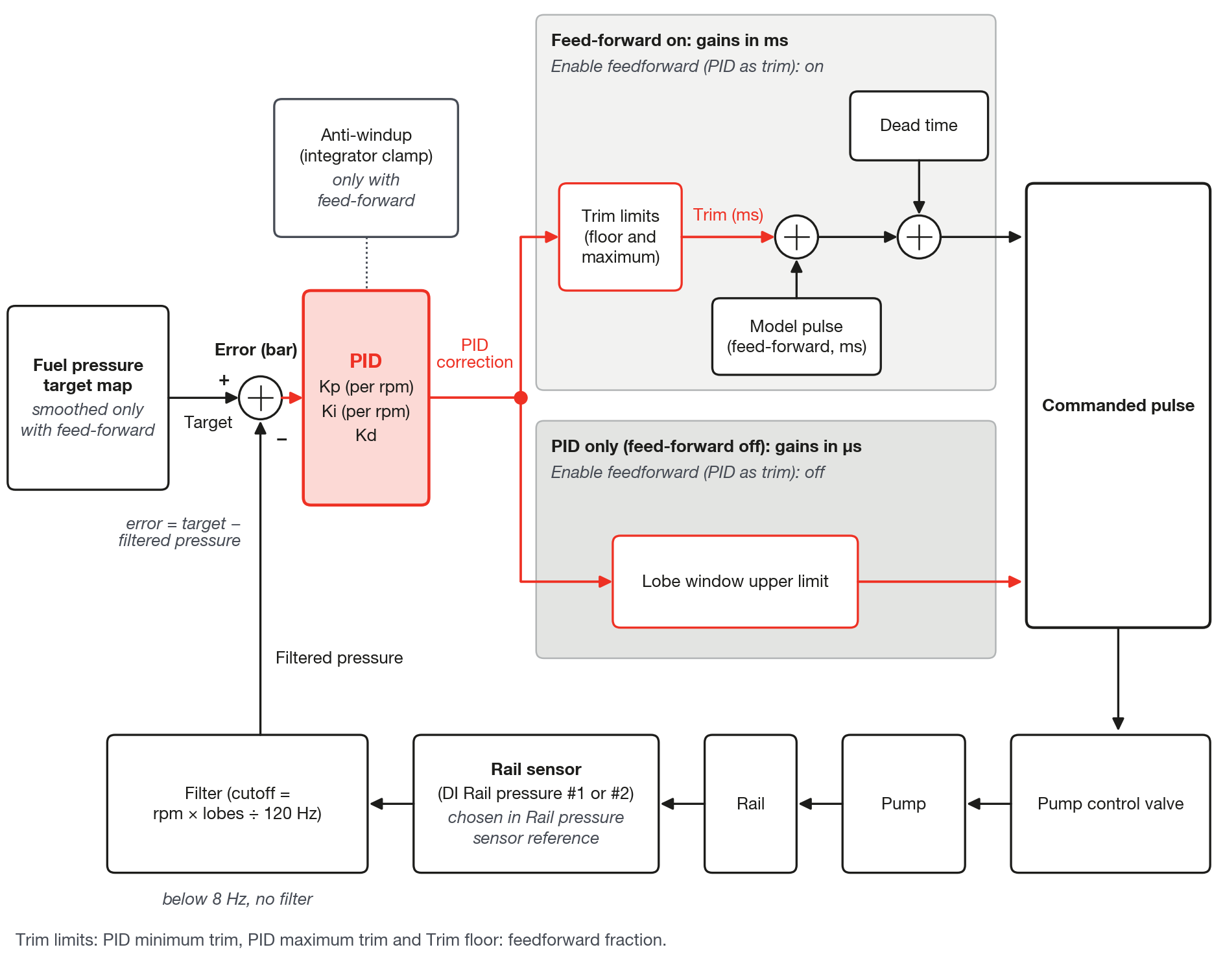
- On: the physical model calculates the base pulse and the PID adds a small correction, the trim, in ms.
- Off: the PID commands the whole pulse, in µs. This is the PID-only mode.
| Aspect | Feed-forward on | PID only (off) |
|---|---|---|
| Valve pulse | Model + PID trim + dead time | PID output, between zero and the window limit |
| Correction limits | PID minimum trim, PID maximum trim and Trim floor: feedforward fraction | Only the window limit |
| Anti-windup (integrator clamp): limit of the accumulated error | Applies | Not used |
| Target smoothing | Yes | No |
| Angled window upper limit and Valve delay (phase advance) | Apply | Do not apply |
| Cranking and injector lockout | Exist | Do not exist |
| Rail sensor faulted | Pulse from the model only, no PID | Pump off |
| Guard 1 and Guard 2 | Apply | Apply |
Cranking, injector lockout and sensor fault are in Cranking and protections.
The window limit is in The lobe angles.
In PID-only mode there is no model: the whole delivery depends on the gains and the window.
#Gain units
The screen shows no unit for Kp, Ki, Kd and Anti-windup.
The unit depends on the mode.
| Field | Feed-forward on | PID only (off) |
|---|---|---|
| Proportional gain Kp (RPM) | ms per bar | µs per bar |
| Integral gain Ki (RPM) | ms per (bar × s) | µs per (bar × s) |
| Derivative gain | ms per (bar/s) | µs per (bar/s) |
| Anti-windup (integrator clamp) | bar × s | Not used |
The fields do not convert units: the gains are per bar even if the screen shows another pressure unit.
#The error
The loop works with the pressure error:
error = target − filtered pressure (in bar)Positive error: the rail is below the target and the loop asks for more pulse.
Negative error: the rail is above the target and the loop asks for less pulse.
The GDI - Pressure error rail 1 channel shows this error in bar, with the same sign. Rail 2 has its own channel.
The channel reads 0 when the rail sensor is in fault or the rail has no active loop. A fixed error of 0 does not prove that the pressure is on target: check it against DI Rail pressure #1 and Fuel pressure rail target - HPFP.
There is no limit on the error: a large error enters the calculation in full. The correction is limited as described below.
#The pressure the loop uses
The loop uses the pressure of the sensor chosen in Rail pressure sensor reference, filtered.
The DI Rail pressure #1 and DI Rail pressure #2 channels show the sensor reading, without the loop filter.
The filter cutoff follows the frequency of the pump strokes, which changes with rpm:
pump strokes per second = rpm × lobes ÷ 120Example: with 3 lobes at 3000 rpm there are 75 pump strokes per second.
Below 8 pump strokes per second the loop uses the unfiltered reading (with 3 lobes, below 320 rpm).
The oscillation of each stroke appears in DI Rail pressure #1. Only what appears in GDI - Pressure error rail 1 or in GDI - PID trim rail 1 reaches the correction.
The filtered pressure is not logged; it is Fuel pressure rail target - HPFP minus GDI - Pressure error rail 1.
With the sensor in fault, the loop keeps the last valid pressure value.
#Kp, Ki and Kd
The PID adds three terms:
correction = Kp × error + Ki × accumulated error + Kd × change in error- Kp reacts to the error right now.
- Ki accumulates the error over time, in bar × s, and removes the difference that is left.
- Kd reacts to the speed at which the error changes.
Proportional gain Kp (RPM) and Integral gain Ki (RPM) are 8-point curves by rpm, each on its own page.
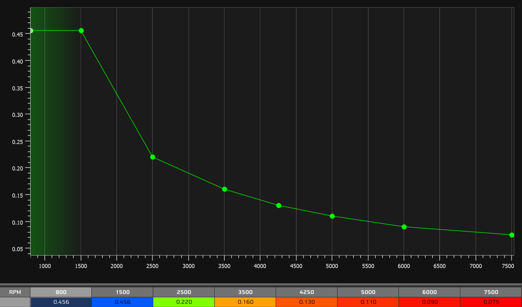
The default axis is 800, 1500, 2500, 3500, 4250, 5000, 6000 and 7500 rpm.
The VCU interpolates between the points. Outside them the edge point applies.
Derivative gain is a single value, on the PID settings page, in the PID (shared between the rails) group.
Kp, Ki and Kd come at 0 in the new map and apply to both rails.
With the VCU connected, the gains and the curves can be edited live.
When Ki changes with rpm, the VCU rescales the integral term so that the correction does not step.
Kd acts on the change in the error, including target changes; the VCU neither filters nor limits this derivative.
This guide gives no starting value for Kd: there is no measured reference.
#Correction limits
With feed-forward on, the PID correction stays between a floor and a maximum.
The fields are in the Transient and trim group of the PID settings page.
maximum = PID maximum trim
floor   = −(the larger of |PID minimum trim| and Trim floor × feed-forward)
trim    = PID correction limited between the floor and the maximum
The defaults are −2.00 ms, +2.00 ms and 50 % for Trim floor: feedforward fraction.
The floor grows in magnitude with the feed-forward: with 50 %, the negative trim can reach half of the feed-forward value, if that is larger than the PID minimum trim in absolute value.
When the correction reaches a limit, GDI - Trim at limit rail 1 goes to 1.
The proportional term alone brings the trim to the limit when the error reaches the trim limit ÷ Kp.
Example: with Kp of 0.5 ms per bar and a limit of 2 ms, 4 bar of error already bring the trim to the limit.
#Anti-windup
While there is error, the accumulated error grows. Anti-windup (integrator clamp) limits this accumulation, in bar × s.
The maximum integral term is therefore Ki × Anti-windup:
maximum integral term (ms) = Ki × Anti-windupExample: Ki of 0.2 with the default Anti-windup (50) gives 10 ms, above the default 2 ms trim limit: the trim limits.
In addition to the clamp, the integrator stops accumulating in the direction in which a limit holds the command.
With the command held at a limit and the rail still below the target, the integrator does not grow.
With the trim held at the floor, or the pulse at zero, and the rail still above the target, the integrator does not decrease.
Limits that count: trim at the maximum or floor, angular limit, lobe window limit, Guard 1 trimming and zero pulse.
The flags GDI - Trim at limit rail 1, GDI - Angular upper limit (max Theta) rail 1, GDI - Lobe window upper limit rail 1 and GDI - Guard 1 trimming rail 1 tell which limit is holding the command.
The zero pulse does not light a flag: it appears as GDI - Commanded pulse rail 1 equal to 0.
This applies with feed-forward on. Without it, the Anti-windup on the screen is not used.
#When the PID stops
With feed-forward on, the PID freezes, keeping the last values, during cranking, in the deceleration cut above 1400 rpm and while the sensor is in fault.
The deceleration cut is in Feed-forward (physical model) and trim.
The integrator resets to zero when the function is turned on, when Guard 2 is released and when the sensor returns after a fault of about 0.5 s or more.
Stopping the engine does not reset the integrator.
#Two rails
The gains, the trim limits, the floor and the Anti-windup are shared: they apply to both rails.
The feed-forward model is also shared: only the trim corrects the difference between the rails.
Each rail has its own reference sensor, integrator and trim: GDI - PID trim rail 1 and GDI - PID trim rail 2.
Since a single set of gains serves both rails, look at both error channels when tuning.
#Why reduce the gain with rpm
Field experience: use smaller Kp and Ki at the higher rpm points of the curve.
The pressure responds more to the same ms of trim the higher the rpm.
A fixed gain over the whole range tends to oscillate at high rpm, with an amplitude that grows with rpm.
Two facts explain the tendency:
pump strokes per second = rpm × lobes ÷ 120
crankshaft degrees per ms = 0.006 × rpm
With 3 lobes, at 3000 rpm there are 75 pump strokes per second and 18 crankshaft degrees per ms.
At 6000 rpm, each ms covers 36 crankshaft degrees.
Fill in the two curves with values that decrease with rpm.
Field experience: with feed-forward on, Kp and Ki at 7500 rpm are close to 40 % of the value at 800 rpm (numbers in the starting values table of Commissioning and tuning step by step).
Cutting gain does not fix a cycle caused by the window phase.
Classify the cycle before touching the gain: see Diagnostics: symptoms and causes.
Set the window and angular limit before the gains: with a wider window at the same Kp, the rail may oscillate more.
The starting values by number of lobes and the complete tuning order are in Commissioning and tuning step by step.
#What the log shows of the loop
| Channel | What it shows |
|---|---|
| Fuel pressure rail target - HPFP | Target used by the loop (smoothed with feed-forward), common to both rails |
| DI Rail pressure #1 and DI Rail pressure #2 | Sensor reading, without the loop filter |
| GDI - Pressure error rail 1 | Target minus filtered pressure, in bar |
| GDI - PID trim rail 1 | PID correction applied (in ms, with feed-forward) |
| GDI - Trim at limit rail 1 | 1 when the correction reaches the floor or the maximum |
| GDI - Angular upper limit (max Theta) rail 1 | 1 when the angular limit cuts the pulse (only with feed-forward) |
| GDI - Lobe window upper limit rail 1 | 1 when the window width cuts the pulse |
| GDI - Guard 1 trimming rail 1 | 1 when Guard 1 trims the pulse |
The flags read 0 when the rail has no active loop.
The log does not record the loop mode: see Reading the log.