9. Reading the log
The pump channels show what the VCU calculated and what it delivered to the valve.
This chapter says which channels to record, what each one means and how to read the duty, the error, the trim, the feed-forward and the pulse.
The rail 2 channels have the same names as those of rail 1, with 2 in place of 1. The names do not follow a single pattern (Duty Rail #1 - HPFP, GDI - Pressure error rail 1): search for the exact name.
#Which channels to record
The channels are in the Datalogger list, with the columns Record, Enabled and Visible.
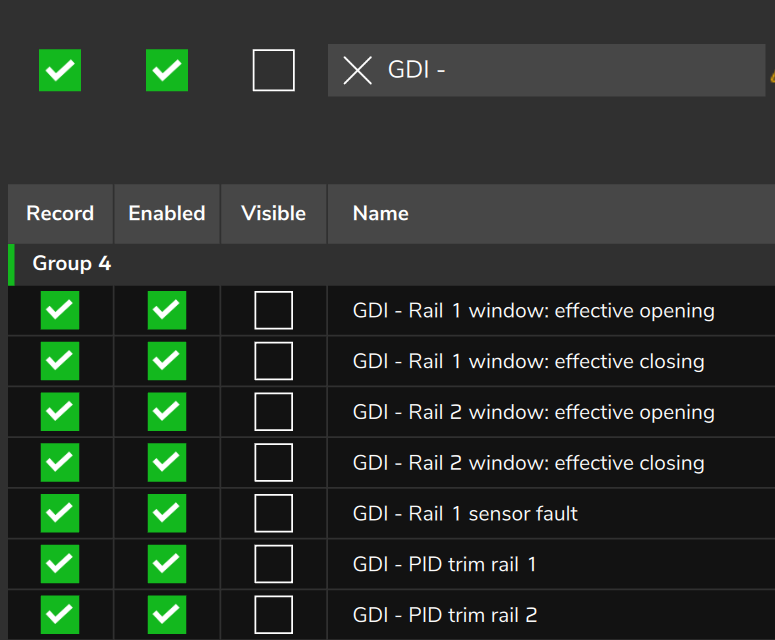
On a new FT700 map, the pump channels come checked in Record and unchecked in Visible. DI Rail pressure #1 and DI Rail pressure #2 come checked in both.
On a new FT470 map, no pump channel comes recording, not even DI Rail pressure #1 and DI Rail pressure #2: check Record on each one.
If a recorded channel does not show on the log graph, check the Visible column.
The recording rate is the datalogger rate (new map: 10 ms on the FT700, 20 ms on the FT470). A channel only has its own rate with Individual sampling rate on.
The log only shows oscillations up to half the rate: at 10 ms, up to 50 per second; at 20 ms, up to 25. The pump strokes (rpm × lobes ÷ 120 per second) exceed that already at medium rpm, such as 75 per second at 3000 rpm with 3 lobes, and appear as a false, slower oscillation, or do not appear.
To tune the pump, record: DI Rail pressure #1, Fuel pressure rail target - HPFP, Duty Rail #1 - HPFP, GDI - Pressure error rail 1, GDI - PID trim rail 1, GDI - Feedforward rail 1, GDI - Commanded pulse rail 1, the four limit signals and the effective window, together with the rpm and the load of the target axis.
#Pressure and command channels
| Channel | Unit | What it means |
|---|---|---|
| DI Rail pressure #1 / DI Rail pressure #2 | bar | Direct reading of the DI1 / DI2 input, without the loop filter. Same basis as the target and the guards. |
| Fuel pressure rail target - HPFP | bar | Target the loop uses, already smoothed with feed-forward on. A single channel for both rails. |
| Duty Rail #1 - HPFP | % | Pulse as a fraction of the window width. 100 in the start routine, 0 with the rail off. |
| GDI - Pressure error rail 1 | bar | Target minus filtered pressure. Positive: rail below the target. Zero if the sensor is not good. |
| GDI - PID trim rail 1 | ms | PID correction, already limited. Zero without feed-forward and in limp-home. |
| GDI - Feedforward rail 1 | ms | Part of the pulse that the model calculates to deliver volume, without dead time and without trim. |
| GDI - Commanded pulse rail 1 | ms | Final pulse, after all the limits. Zero in the deceleration cut, with the rail off and in the start routine. |
| GDI - Rail 1 window: effective opening and GDI - Rail 1 window: effective closing | crankshaft degrees | Start and end of the actual pulse, from 0 to 720. |
#How to read the duty
The duty is not the duty cycle of a PWM. It is the pulse divided by the window upper limit, in %.
The window upper limit is the width of the lobe #1 window converted to time by the current rpm:
window upper limit (ms) = window width ÷ (0.006 × rpm)
pulse (ms)              = duty ÷ 100 × window upper limit
The window width is the closing minus the opening, in crankshaft degrees. The factor 0.006 × rpm is the crankshaft degrees per millisecond.
Example: a 120 crankshaft degree window at 3000 rpm gives an upper limit of 6.67 ms. A duty of 40 % is a pulse of 2.67 ms.
The same pulse gives a different duty on maps with different windows. To compare maps, use GDI - Commanded pulse rail 1.
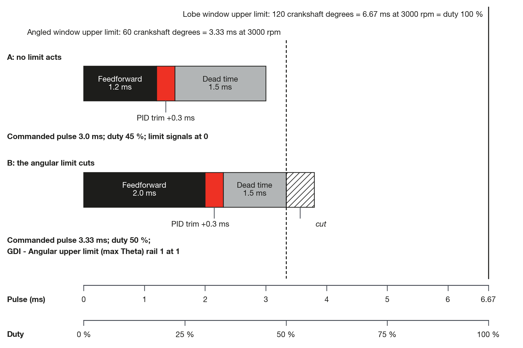
With feed-forward on and the factory defaults (60 degree angular limit against a 120 degree window), the duty stops at 50 %. Without feed-forward there is no angular limit.
#Error, trim, feed-forward and pulse
With feed-forward on and no limit acting, the pulse is built like this:
commanded pulse = feed-forward + trim + dead timeThe dead time is the Valve base dead time (t0) plus the Battery voltage based dead time curve. It has no channel.
Check: pulse minus (feed-forward + trim) should give the dead time. If it gives less with a pulse greater than zero, a limit cut the pulse: see the limit signals. If feed-forward plus trim is zero or less, the pulse is zero.
GDI - Feedforward rail 1 keeps showing the calculated value even with the pulse at zero.
Trim near zero at steady state: the model is right. Trim always on the same side: the model is wrong and the PID compensates (see Commissioning and tuning step by step).
The error is positive with the rail below the target, and the PID asks for more pulse.
The error is calculated on the filtered pressure, which is not recorded. So it is not equal to target minus DI Rail pressure #1, which is the direct reading. The filtered pressure is the target minus the error.
#Effective window
GDI - Rail 1 window: effective opening and GDI - Rail 1 window: effective closing show where the pulse fell in the 720 crankshaft degree cycle, counted from the TDC of cylinder 1.
The effective closing is the end of the pulse: Lobe #1 closing angle, shifted by the cam deviation and advanced by the Valve delay (phase advance).
The effective opening is the start of the pulse: the effective closing minus the degrees of the pulse (0.006 × rpm × pulse in ms).
With zero pulse, the effective opening and the effective closing are equal. Both at 0 indicate rail off or start routine (see Cranking and protections).
The phase sweep of the closing is in The lobe angles.
#Limit and state signals
These channels are 0 or 1.
| Channel | At 1 when |
|---|---|
| GDI - Trim at limit rail 1 | the PID was cut at the lower limit (PID minimum trim or Trim floor: feedforward fraction) or at PID maximum trim, at this instant |
| GDI - Angular upper limit (max Theta) rail 1 | the command went above the Angled window upper limit and was cut |
| GDI - Lobe window upper limit rail 1 | the pulse went above the window width and was cut |
| GDI - Guard 1 trimming rail 1 | Guard 1 is active and the pulse went above its limit |
| GDI - Rail 1 sensor fault | the sensor is suspected or declared failed |
| GDI - Rail 1 in limp-home | the sensor is declared failed |
| GDI - Overpressure cut rail 1 | Guard 2 shut the rail pump off |
The first four say which limit holds the pulse when the rail is below the target and the pulse does not grow. The smaller of the two window limits applies, and both signals can light up together.
The last three are in Cranking and protections.
The four limit signals stay at 0 when there is no loop: rail off, start routine and Guard 2.
Zero pulse, from lack of demand or deceleration cut, has no signal of its own: the signal is GDI - Commanded pulse rail 1 at 0, and GDI - Trim at limit rail 1 can be at 1 at the same time.
#Reading in order
In a stretch where the rail does not hold the target, read in this order:
- DI Rail pressure #1 against Fuel pressure rail target - HPFP: is the rail below or above the target?
- GDI - Pressure error rail 1: the signal confirms the direction.
- GDI - Commanded pulse rail 1 and the duty: does the pulse grow when the error grows?
- If the pulse does not grow, the limit signals say which limit holds it. With GDI - Angular upper limit (max Theta) rail 1 or GDI - Lobe window upper limit rail 1 at 1 and the rail below the target, the limit is a configuration one.
- Duty 0 with the engine running: check Engine Sync, the effective window at 0 / 0 and GDI - Overpressure cut rail 1 (see Diagnostics: symptoms and causes).
#What the log does not record
There are no channels for the filtered pressure, for the loop mode (start, deceleration cut or normal), for the injector cut done by the pump and for the advance applied to the window.
The mode is deduced from the set: start is duty 100 with low rpm and commanded pulse at 0; deceleration cut is zero pulse with the pressure more than 10 bar above the target.
Active cut (inj) shows the code of the engine injection cut, not the injector cut done by the pump.
Engine Sync at 0 means the pump is not driven.
Intake cam position #1 (and exhaust 1, intake 2, exhaust 2) shows the cam deviation, not the absolute position, in crankshaft degrees. Check this deviation before turning on Cam dependence.
#Chart scales
The default chart scale of DI Rail pressure #1 and DI Rail pressure #2 is from -2000 to 2000: adjust it to see the rail.
The default scale of GDI - Feedforward rail 1 and GDI - Commanded pulse rail 1 is from 0 to 20 ms: adjust it if the pulse goes above that.