4. The lobe angles
The lobe angles tell the VCU at what point of the cycle the pump delivers.
This is where most questions come up: what degree they are at, what each field does and why the rail does not hold pressure when they are wrong.
This chapter explains each field, shows how the VCU builds the window of each lobe and gives a method to find the angles on a new engine.
For what the lobe, the valve and the pump stroke are, see How the pump delivers fuel.
#The fields on the screen
The fields are in Other Functions > High pressure fuel pump (HPFP), tab Settings, page General settings, in the Rail #1 block (and Rail #2, with 2 rails).
On the phone, each rail has its own page.
Angled window upper limit and Valve delay (phase advance) are in the Pump model group, on the PID settings page of the PC.
| Field | What it does | Range (default) |
|---|---|---|
| Number of lobes per cycle | How many cam lobes drive the pump | 1 to 4 (3) |
| Lobe #1 opening angle | Earliest start of the pulse; sets the width | 0 to 720 crankshaft degrees (60°) |
| Lobe #1 closing angle | End of the pulse, near the lobe peak | 0 to 720° (180°) |
| Windows of the other lobes (calculated) | Shows lobes 2 to N; read-only | with 2 or more lobes |
| Cam dependence | Makes the window follow a variable cam | 5 options (None) |
| Valve delay (phase advance) | Advances the whole pulse, more as rpm rises | 0 to 5 ms (0) |
| Angled window upper limit | Maximum pulse duration, in crankshaft degrees | 10 to 180° (60°) |
#Where the angles are counted from
The angle fields show no unit on the screen.
They are crankshaft degrees, from 0 to 720 per 4-stroke cycle.
0 is the TDC of cylinder 1, the same origin as the injection and ignition angles.
A larger number is later in the cycle.
One camshaft degree equals 2 crankshaft degrees: the lobe angles are never camshaft degrees.
The VCU adds the Crank index position to these angles.
If it is wrong, the pump window, the injection and the ignition are all shifted by the same amount.
Recommended practice: confirm TDC with a timing light before tuning the pump.
#Number of lobes and spacing
Set Number of lobes per cycle to the number of lobes on the cam that drives the pump.
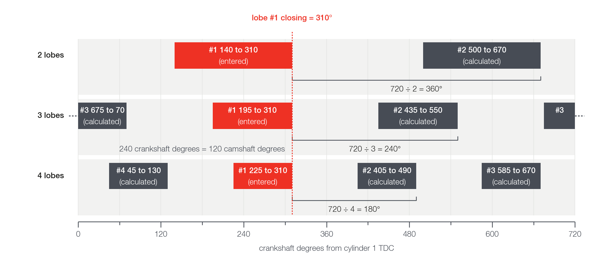
The lobes are equally spaced: the spacing is 720 ÷ number of lobes.
| Lobes | Between lobes (crankshaft) | Between lobes (camshaft) |
|---|---|---|
| 1 | 720° | 360° |
| 2 | 360° | 180° |
| 3 | 240° | 120° |
| 4 | 180° | 90° |
You configure only lobe #1.
The VCU repeats its window on the other lobes, shifted by 720 ÷ N.
All lobes of a rail use the same pulse.
Only the angle changes from one lobe to the next.
There is no per-lobe spacing adjustment: the spacing is fixed.
#Opening, closing and width
The Lobe #1 closing angle is where the pulse ends, near the lobe peak.
It is not the exact peak: the value found by sweeping is a few degrees before it.
Field experience: 9 to 13 crankshaft degrees before the pump peak.
The Lobe #1 opening angle is the earliest start the pulse can have.
The difference between the two is the window width, the ceiling of the pulse duration.
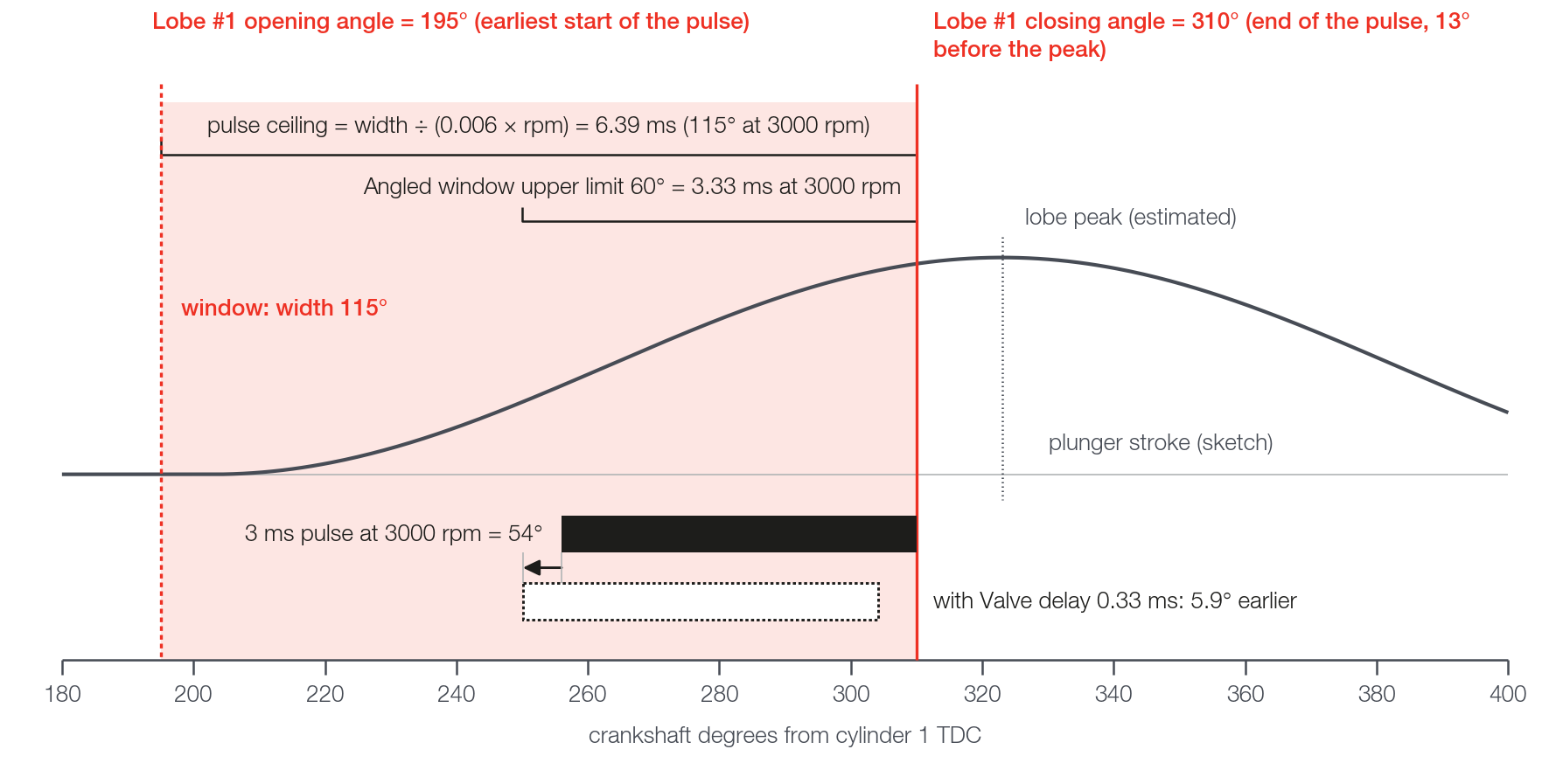
The VCU calculates the start at every instant: pulse start = closing − pulse duration in degrees.
The opening does not move the pulse: it only sets the width.
width (degrees) = closing − opening
pulse ceiling (ms) = width ÷ (0.006 × rpm)
0.006 × rpm is how many crankshaft degrees pass in 1 ms: 6° at 1000 rpm, 18° at 3000 rpm, 36° at 6000 rpm.
| Width | 1000 rpm | 3000 rpm | 6000 rpm |
|---|---|---|---|
| 85° | 14.17 ms | 4.72 ms | 2.36 ms |
| 120° | 20.00 ms | 6.67 ms | 3.33 ms |
| 170° | 28.33 ms | 9.44 ms | 4.72 ms |
Besides the cam shift, two situations make the pulse not end at the closing you entered:
- With Valve delay (phase advance) above 0 and feed-forward on, the whole pulse comes earlier (section below).
- During cranking, with feed-forward on, the valve stays on continuously, with no angular end: see Cranking and protections.
The duty in the log is the pulse divided by the width ceiling, width ÷ (0.006 × rpm).
If you move only the closing, the width changes and the duty changes, even with the same physical pulse.
Compare adjustments with the GDI - Commanded pulse rail 1 channel, in ms.
#Invalid window
The VCU turns the rail off in two cases.
Zero or negative width: closing less than or equal to opening.
Width greater than or equal to 720 ÷ N: the windows of neighboring lobes overlap.
The width must stay below 720°, 360°, 240° and 180° crankshaft with 1, 2, 3 and 4 lobes.
The factory default (60° and 180°) gives a width of 120°, which passes with 1 to 4 lobes.
Rail off: output off, duty 0 and effective window 0/0.
The effective window 0/0 also appears without engine sync and during cranking.
FuelTech Vision reports the error in the map diagnostics list, when opening the map and when confirming the function.
The warning does not block.
When editing live, an invalid intermediate value turns the rail off immediately: to retard, move the closing first; to advance, move the opening first (see Live editing).
#Windows of the other lobes (calculated)
With 2 or more lobes, the screen shows one line per lobe, from #2 to #N: "Lobe #n: opening x° / closing y°".
It is read-only.
Each value is the lobe #1 value plus (n − 1) × 720 ÷ N, wrapping back to 0 after 720.
The list shows the values you entered: it does not include cam, valve delay or the real pulse width.
Example, 3 lobes, opening 195° and closing 310° crankshaft: lobe #2 from 435° to 550°; lobe #3 from 675° to 70°.
Lobe #3 looks inverted, but it is not: the window passes 720 and wraps to 0.
That is 45° up to 720 plus 70°, or 115°: the same width as lobe #1.
Only lobe #1 is validated, and on it the closing must be greater than the opening.
If the window you want would cross 0, add 720 ÷ N to both angles of lobe #1.
With 3 lobes, a window from −40° to 80° is equivalent to one from 200° to 320°: the set of windows is the same.
#Cam dependence
The options are None, Intake #1, Intake #2, Exhaust #1 and Exhaust #2, one choice per rail.
Use only when the pump is driven by a cam with variable timing (VVT) and the cam sensor is reading.
Without VVT, leave None.
With a cam selected, the window follows the measured deviation of that cam.
A retarded cam moves the window later, by the same amount; an advanced cam, earlier.
The shift is limited to 90° crankshaft.
Enter the angles with the cam at its rest position.
If the deviation is not valid, the window has no shift.
The Intake cam position #1 channels (and exhaust 1, intake 2, exhaust 2) show the cam deviation, not the absolute position.
Recommended practice: before turning it on, record the deviation in the log and check that it stays near 0 with the cam at rest and changes when the VVT acts.
After turning it on, at constant rpm, when the cam channel rises by one value the GDI - Rail 1 window: effective closing must fall by the same value.
#Valve delay (phase advance)
The advance is 0.006 × rpm × delay, in crankshaft degrees, with the delay in ms (0 to 5, default 0).
It advances the whole pulse, start and end, without changing the duration.
With a 0.33 ms delay: 2.0° at 1000 rpm, 5.9° at 3000 rpm, 11.9° at 6000 rpm and 14.9° at 7500 rpm.
A fixed valve delay, in ms, takes up more degrees the higher the rpm: the field advances the pulse in the same proportion.
It acts only with Enable feedforward (PID as trim) on.
Without feed-forward the advance is zero, even with the field filled in.
There is no channel for the advance: it appears built into the GDI - Rail 1 window: effective closing.
With Cam dependence at None, advance = entered closing − effective closing, modulo 720.
Recommended practice: use the delay only if the needed advance grows with rpm across the whole range.
If the best phase is the same at every rpm, leave 0 and shift the angles: the delay would be wrong at the rpm where the needed advance is smaller.
#Angled window upper limit and which ceiling applies
Angled window upper limit is the maximum pulse duration, in crankshaft degrees, counting the valve dead time.
With Enable feedforward (PID as trim) on, the pulse never exceeds the smaller of the Angled window upper limit and the window width:
pulse ceiling (ms) = smaller(Angled window upper limit; width) ÷ (0.006 × rpm)Example at 3000 rpm, width 115° and Angled window upper limit 60°: the width gives 6.39 ms and the Angled window upper limit gives 3.33 ms.
The value is 3.33 ms.
At the defaults (Angled window upper limit 60°, width 120°), with feed-forward on, the maximum duty is 50%.
If the width is smaller than the Angled window upper limit, the Angled window upper limit does not act.
Without feed-forward only the width limits the pulse.
To see which ceiling holds the command, use GDI - Angular upper limit (max Theta) rail 1 (max Theta is the Angled window upper limit itself) and GDI - Lobe window upper limit rail 1.
More on the ceiling in Feed-forward (physical model) and trim.
#Checking the angles in the log
In the channel names, replace "rail 1" with "rail 2" for the second rail.
GDI - Rail 1 window: effective closing = entered closing + cam shift − advance.
GDI - Rail 1 window: effective opening is the start of the real pulse, not the opening angle you entered.
With zero pulse, the effective opening is equal to the effective closing.
When the pulse crosses 0, the effective opening is greater than the effective closing: this is normal.
For duty, pulse and ceiling flags, see Reading the log.
#Live editing
With the VCU connected, each step in the fields Number of lobes per cycle, Lobe #1 opening angle, Lobe #1 closing angle, Cam dependence, Valve delay (phase advance) and Angled window upper limit goes to the VCU immediately.
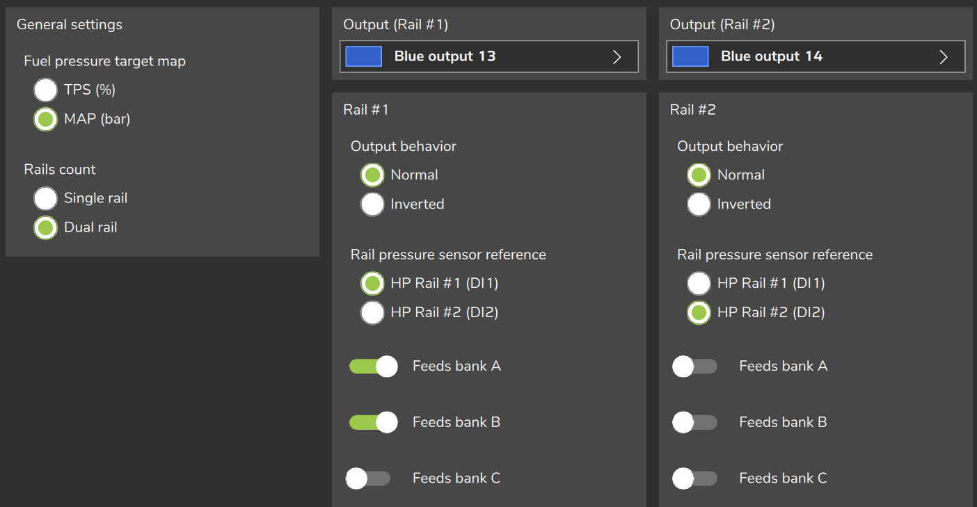
Output (Rail #1), Output behavior, Rail pressure sensor reference and Rails count only take effect after you write the map and restart the VCU: see Before you start: installation.
To retard the window, increase the closing first and then the opening.
To advance, move the opening first and then the closing.
This way the window is never inverted in the middle of the adjustment.
Moving only the closing changes the width, the pulse ceiling and the duty.
To change the phase without changing the width, move both by the same value, in the order above.
When you finish, write the map.
#Two pumps (V engine)
With 2 rails, each rail has its own output, sensor, Cam dependence, number of lobes, opening and closing.
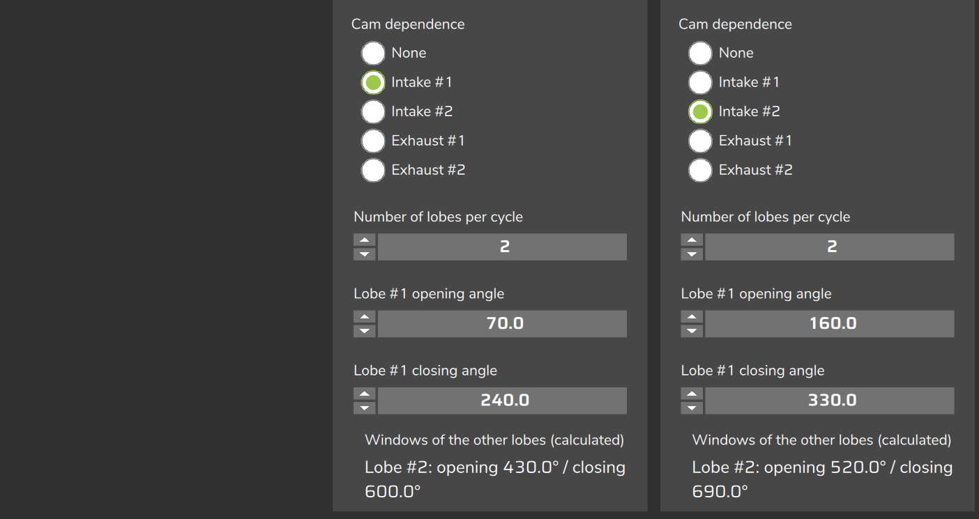
Angled window upper limit, Valve delay (phase advance), gains and curves are shared by both.
There is no automatic offset: the offset between the pumps is the difference between the closings of the two rails.
The windows of the two rails can overlap without error, because validation is per rail.
Field experience: start the angles of Rail #2 from those of Rail #1 plus the engine V angle, added in crankshaft degrees; then confirm with the sweep of step 5 of Commissioning and tuning step by step.
Recommended practice: tune one rail at a time, keeping the angles of the other fixed, and compare the pulse and trim of each one in the rail 1 and rail 2 channels.
This way you know which change caused each effect.
#How to find the angles on a new engine
The phase sweep is done by you, with live editing of the angles and the effective window, duty and pulse channels.
The pump lobe peak comes from outside FuelTech Vision: cam card, pump manufacturer or estimate.
Without the cam card, ask the pump or cam manufacturer for the data: the starting point of the sweep comes from it.
Before: pressure sensor reading, protections and output polarity ready (see Commissioning and tuning step by step).
Also check the Crank index position and leave Cam dependence at None.
#Starting point
- Estimate the pump lobe peak from the cam card or the manufacturer data, in crankshaft degrees from cylinder 1 TDC.
- Set the closing about 10 to 15° before the peak (recommended practice).
- Calculate the opening: closing − (360 ÷ N − 5 to 10°).
- Check that the window is valid: no error in the diagnostics list, Engine Sync at 1 and effective window other than 0/0.
The starting width comes from field experience: 360 ÷ N is half the spacing between lobes.
| Lobes | 360 ÷ N | Starting width | Opening, with example closing of 310° |
|---|---|---|---|
| 2 | 180° | 170° to 175° | 135° to 140° |
| 3 | 120° | 110° to 115° | 195° to 200° |
| 4 | 90° | 80° to 85° | 225° to 230° |
#Phase sweep
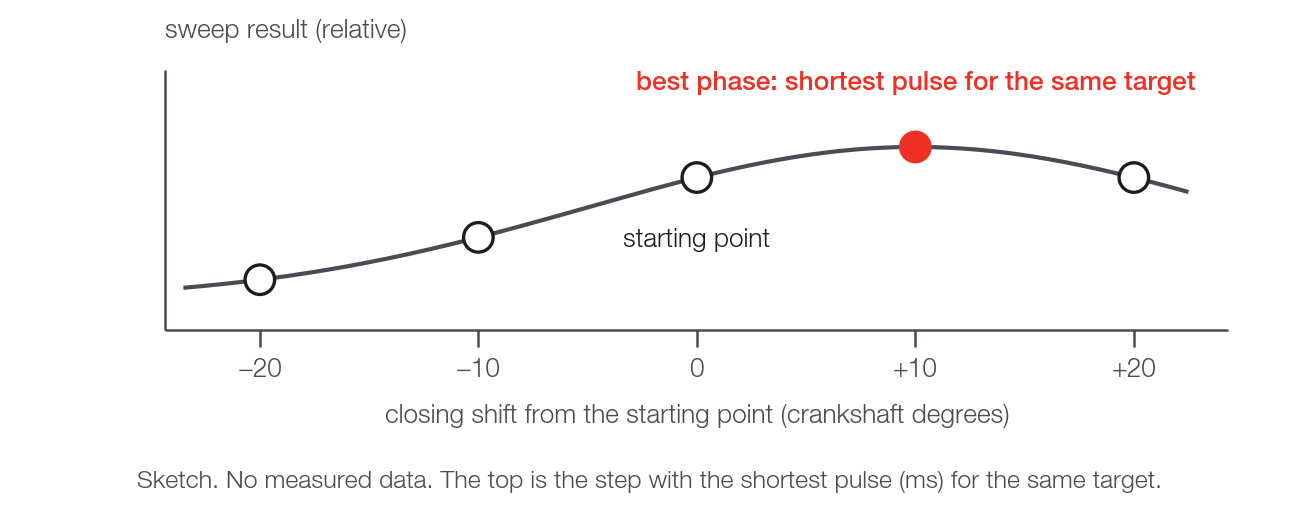
- Field experience: sweep the closing at steady state, at idle and then near 2500 rpm.
- Use steps of 10°, from −20° to +20° around the initial value, 20 to 30 s per step.
- At each step move opening and closing together, by the same value: the width does not change.
- Keep rpm and load the same at all steps.
- At each step read GDI - Commanded pulse rail 1 (ms), GDI - PID trim rail 1 and GDI - Pressure error rail 1.
- Keep the step where the pressure holds the target with the smallest pulse. If it falls at the edge of the swept range, repeat the sweep with the range centered on it (recommended practice).
- Repeat at a second rpm.
- If the best step moves earlier, in proportion to rpm, see Valve delay (phase advance).
- If it does not move, or moves later, the delay does not fit: keep the angles fixed and leave the delay at 0.
Field experience: the sweep result forms a bell shape against the shift, and the top is the step with the smallest pulse.
#Window width
- Only after the phase, adjust the width, always with the opening, so as not to move the phase.
- A window that is too narrow saturates the command.
- Field experience: a wider window gives more authority and, with the same gain, may oscillate more.
- Widen only if GDI - Lobe window upper limit rail 1 is active with the rail below the target (positive error).
- Before widening, check the margin between the maximum pressure and the guards: field experience, at least about 10 bar.
- Adjust the gains after the width: see Closed loop and PID.
#Frequently asked questions
Are the angles crankshaft degrees from TDC?
Yes. Opening and closing go from 0 to 720 and count crankshaft degrees from cylinder 1 TDC.
Is "3 lobes = 120 degrees" correct?
Only in camshaft degrees. 3 lobes are 120° camshaft, which is 240° crankshaft.
4 lobes are 90° camshaft, which is 180° crankshaft.
The fields on the screen use crankshaft degrees.
Is the lobe window width (spread) adjustable?
The window width, closing minus opening, is adjustable: it is the pulse ceiling.
The spacing between lobes is fixed at 720 ÷ N.
Is the closing angle the lobe peak?
No. It is where the pulse ends, near the peak.
The value found by sweeping is a few degrees before the peak.
Is the opening angle the start of the lobe lift?
No. It is the earliest start the pulse can have.
It does not move the pulse: it only sets the width.
Why does the screen show a lobe with opening greater than closing?
On the calculated lobes the window can pass 720 and wrap to 0, such as 675° to 70°.
Only lobe #1 needs closing greater than opening.
How is the angle sweep done?
By you, with live editing and the effective window, duty and pulse channels: see How to find the angles on a new engine.
Why does the rail not hold pressure?
Phase out of place, a window that is too narrow and an invalid window are among the causes.
The Diagnostics: symptoms and causes table separates each one.