8. Cranking and protections
This chapter explains what the pump does from the first turn of the starter until normal running, and what the VCU does when the pressure or the sensor leaves the expected range.
The fields are on the Protection settings page, in the groups Engine start, Protections (guards) and Low rail pressure injector cut-off (on the phone and on the panels, in a single list).
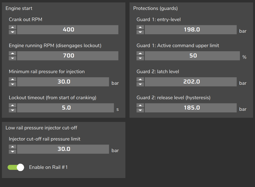
Enter the target, guards, minimum pressure and cut-off limit on the same basis as the reading of the DI Rail pressure #1 channel (or DI Rail pressure #2): the VCU does not add or subtract atmospheric pressure.
#Cranking step by step
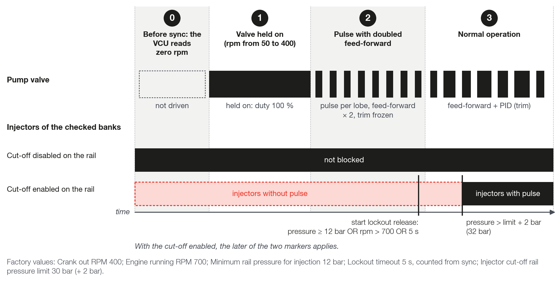
The pump start has four stages. The values in parentheses are the factory defaults.
- Before sync. The VCU only treats the engine as turning after it synchronizes the trigger wheel (with a phase sensor, after it confirms the phase). Until then it reads zero rpm and the pump valve is not driven. The Lockout timeout (from start of cranking) counts from that point, not from the first turn of the starter.
- Valve held on. With rpm between 50 and Crank out RPM (400 rpm), the valve stays in the delivery state the whole time (energized with Normal, de-energized with Inverted): duty 100 %, no pulse per lobe. This stage does not look at pressure and lasts at most the Lockout timeout (from start of cranking) (5 s). The Angled window upper limit and Guard 1 do not limit this stage; Guard 2 still applies and can shut the pump off.
- Pulse with doubled feed-forward. When the rpm reaches Crank out RPM and the pressure is still below Minimum rail pressure for injection (12 bar) with the timeout not yet expired, the pump pulses inside the window with the part of the pulse that delivers volume multiplied by 2 and the PID trim frozen. The Angled window upper limit, the window width and Guard 1 apply. If the timeout expires before the rpm reaches Crank out RPM, the valve stops being held on and the pump moves to this stage.
- Normal operation. The start ends when the rpm reaches Crank out RPM and, in addition, the pressure reaches Minimum rail pressure for injection or the timeout expires. With two rails, the higher pressure among the rails with a good sensor applies to both. The start rearms when the rpm falls below 50.
In the log, stage 2 shows as Duty Rail #1 - HPFP at 100 with GDI - Commanded pulse rail 1 at 0 ms (see Reading the log).
After the start the pump works with feed-forward and PID (see Feed-forward (physical model) and trim).
#Injector lockout at start
The injector lockout withholds the pulse from the injectors of the rail banks until the start pressure has built up.
The switch is Enable low-pressure injector cut-off (Rail #1); on the PC, Enable on Rail #1. The same switch turns on the low pressure cut-off.
When off, no injector is blocked, neither at start nor while running.
The blocked injectors are those of the banks checked in Feeds bank A / B / C of the rail. A bank that is not checked is never touched.
On the blocked banks the injection time goes to zero. The ignition is not cut and the pump is not commanded by this lockout.
With no bank checked the lockout has no effect; FuelTech Vision shows a warning in the map diagnostics list.
The lockout arms with rpm below 50, and its state is a single one for both rails. It releases when any one of these conditions happens:
- the pressure reaches Minimum rail pressure for injection (12 bar);
- the rpm goes above Engine running RPM (disengages lockout) (700 rpm);
- the Lockout timeout (from start of cranking) expires (5 s).
Once released, the lockout only arms again with the rpm below 50.
#Low pressure injector cut-off
The cut-off applies with the engine running, with or without feed-forward.
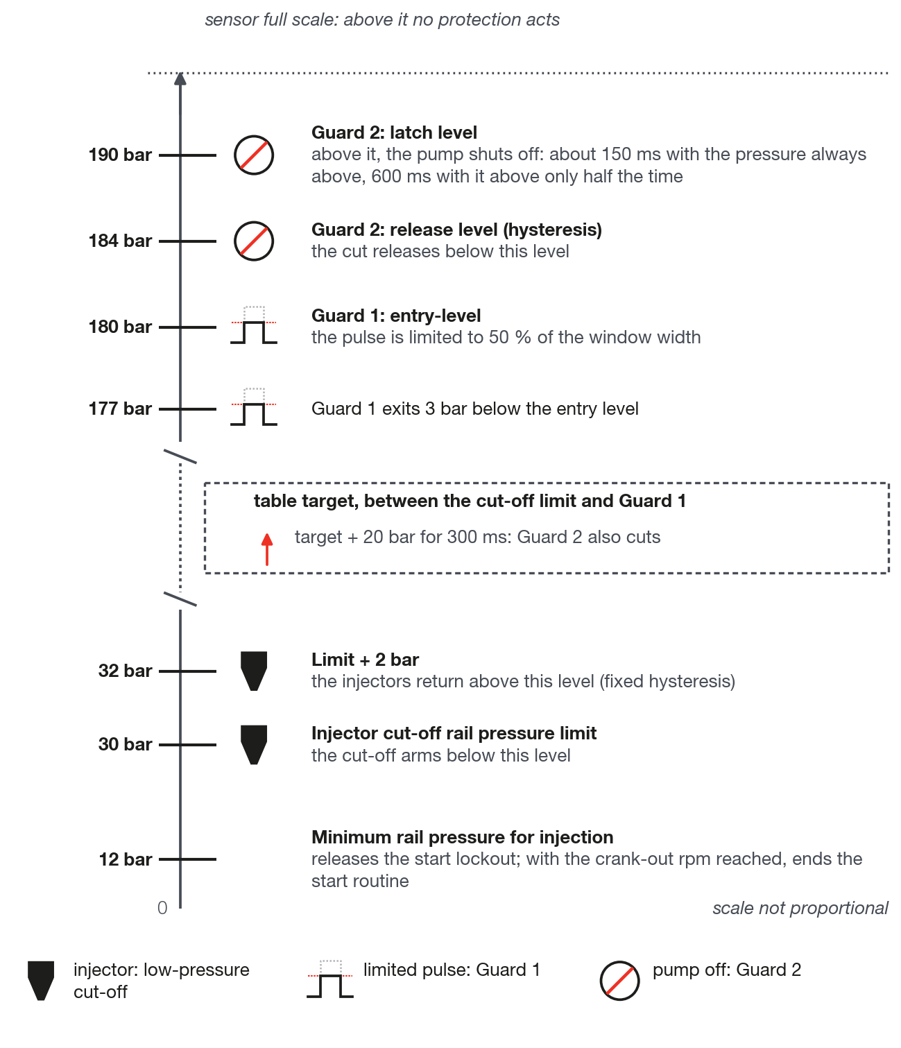
It arms when the rail pressure falls below Injector cut-off rail pressure limit (30 bar). It releases only when the pressure goes above the limit plus 2 bar (32 bar). Between the two values the previous state continues.
When cut, the injectors of the checked banks have no pulse.
The VCU evaluates the filtered pressure, the same one the loop uses. With the rail sensor in fault, the cut-off state stays frozen at the last valid value.
Confirm that DI Rail pressure #1 (or DI Rail pressure #2) reads a valid pressure before you enable the cut-off.
The cut-off does not appear in Active cut (inj) and has no channel of its own: the signal is the bank injection time at zero.
#Guard 1
Guard 1 limits the pulse when the pressure goes above the safety level, without shutting the pump off.
It engages when the pressure goes above Guard 1: entry-level (180 bar) and exits when the pressure falls 3 bar below that level.
When active, the pulse is limited to a fraction of the lobe window width, given by Guard 1: Active command upper limit (50 %). It never replaces the command: it only cuts what goes above the limit.
It applies with and without feed-forward. It does not apply in the valve held on stage of the start.
With feed-forward on, Guard 1 limits the pulse when the window width times the percentage is smaller than the Angled window upper limit: for it to limit, set the percentage times the width below the angular limit. With the defaults (120 crankshaft degree window and 50 %), the Guard 1 limit is 60 degrees, equal to the default angular limit. Without feed-forward there is no angular limit, and it limits already at the defaults.
The signal in the log is GDI - Guard 1 trimming rail 1. It only lights up when Guard 1 is active and the calculated pulse goes above the limit.
Keep the maximum target below Guard 1, with margin. With a target above 180 bar, raise both guards.
#Guard 2
Guard 2 shuts the rail pump off when the pressure is too high. It cuts only the pump, never the injectors: with the pump cut, the rail pressure falls through the injectors' consumption.
Either of these two conditions turns on the cut:
- Level. The VCU counts the time the pressure stays above Guard 2: latch level (190 bar) and subtracts half of the time it stays below. With the pressure always above, the cut comes in about 150 ms. With the pressure above only half of the time, it comes in about 600 ms. Short peaks do not cut.
- Target plus 20 bar. The pressure is more than 20 bar above the target, not falling, for 300 ms in a row. The 20 bar value is fixed and does not appear on the screen. This condition requires a good sensor and, with feed-forward on, does not apply at start or in the deceleration cut.
The level condition also applies during the start.
The cut releases when the pressure falls below Guard 2: release level (hysteresis) (184 bar). On release, the PID restarts without accumulation.
Stopping the engine does not release the cut: it releases with the pressure below the release level or on a VCU restart.
In the log, the signal is GDI - Overpressure cut rail 1 at 1, with duty 0.
#Rail sensor fault
The VCU considers a fault an invalid signal (sensor disconnected, shorted or not configured) or a jump of more than 20 bar between two consecutive readings.
The fault has three moments:
- Suspected. On the first fault, the VCU freezes the reading at the last good value and freezes the PID trim. The pump continues with the feed-forward and the frozen trim; without feed-forward, the PID command is frozen. The GDI - Rail 1 sensor fault channel goes to 1.
- Declared failed. With about 0.5 s of accumulated fault (good readings in between do not discount), the sensor is declared failed. With feed-forward on, the pump enters safe mode (limp-home): pulse from the model only, with no trim and no PID, with the angular limit, the window width and Guard 1 applying. With feed-forward off, the pump is shut off. The GDI - Rail 1 in limp-home channel goes to 1 and the screen shows the alert.
- Recovery. With about 2 s in a row of good signal, the sensor returns to normal. If it had been declared failed, the PID restarts from zero. Any fault in this interval restarts the count.
The alert and the channel say safe mode (limp-home) even without feed-forward; in that case the pump is shut off.
With the sensor declared failed there is no start routine: if that happens during cranking, the valve stops being held on. The end of the start and the injector lockout then depend on the timeout (the lockout also releases through Engine running RPM (disengages lockout)).
#When the rail shuts off
In these cases the rail is off, or the function does not even start. With the rail off the valve does not deliver, the duty goes to 0 and the effective window stays at 0 / 0.
| Condition | What you see or check |
|---|---|
| Engine without sync | Engine Sync at 0 |
| Invalid or zero rpm | Check the rpm in the log |
| Lobe #1 window with zero or negative width | Error in the FuelTech Vision diagnostics list |
| Window width greater than or equal to 720 ÷ number of lobes | Error in the FuelTech Vision diagnostics list |
| Guard 2 active | GDI - Overpressure cut rail 1 at 1 |
| Sensor declared failed, feed-forward off | GDI - Rail 1 in limp-home at 1 and the sensor alert |
| Function with no output assigned: the function does not even start (with 2 rails, a rail without an output stops both) | No pump channel moves |
With the engine stopped (programmed stop, password protection, compression test, alarm), the pulses do not fire, but the duty channel keeps showing the calculated value.
Zero pulse is not rail off. With zero pulse, the effective opening and the effective closing are equal. With the rail off, both are at 0 (see Reading the log).
#Alerts and signals in the log
The pump has a single alert on the screen. It appears once, when the rail sensor is declared failed, as a notice on the screen and in the VCU alert list.
- Title: GDI: rail pressure sensor fault
- Description: High pressure pump in safe mode (limp-home): control loop without pressure sensor correction
- Suggestion: Check the rail pressure sensor, harness and connector
The alert applies to both rails: see which one failed in GDI - Rail 1 sensor fault and GDI - Rail 2 sensor fault.
Start routine, lockout, low pressure cut-off, Guard 1 and Guard 2 appear only in the log (the rail 2 channels swap 1 for 2):
| Event | Signal in the log |
|---|---|
| Start routine | Duty Rail #1 - HPFP at 100 with GDI - Commanded pulse rail 1 at 0 ms |
| Injector lockout and cut-off | Bank injection time at zero; no channel of its own |
| Guard 1 | GDI - Guard 1 trimming rail 1 at 1 |
| Guard 2 | GDI - Overpressure cut rail 1 at 1 |
| Sensor suspect | GDI - Rail 1 sensor fault at 1 |
| Sensor declared failed | Also GDI - Rail 1 in limp-home at 1 |
#When a change takes effect
With the VCU connected, these take effect immediately: Minimum rail pressure for injection, Lockout timeout (from start of cranking), the guard levels, Injector cut-off rail pressure limit, the cut-off enable and the banks of each rail.
Crank out RPM and Engine running RPM (disengages lockout) only take effect after you write the map.
Turning the function on or off and writing the map restarts the VCU by itself, with the engine stopped.