3. Before you start: installation
This chapter lists what must be installed and configured before you turn on the High pressure fuel pump (HPFP) function.
Some omissions make the function not start or run with the wrong signal: the chapter ends with a checklist for the first start.
The pump needs four things: one output per rail, one pressure sensor per rail, the direct injection banks marked and a phase sensor. With VVT (variable valve timing), the cam sensor is added.
The installation differences on the FT470 are in the section FT700 and FT470.
#The pump output
#Which outputs work
The screen accepts the function on any blue, gray or yellow output (the screen divides the VCU outputs into these three color groups). There is no restriction by color.
| VCU | Blue | Gray | Yellow |
|---|---|---|---|
| FT700 (50 outputs) | 16 | 12 | 22 |
| FT470 (20 outputs) | 8 | 8 | 4 |
Assign the output with the Output (Rail #1) button: on the PC, on the General settings page; on the phone, on the tablet and on the panels, on the Rail #1 page.
In the output list the function appears as High pressure fuel pump (HPFP) - Rail #1 (and - Rail #2).
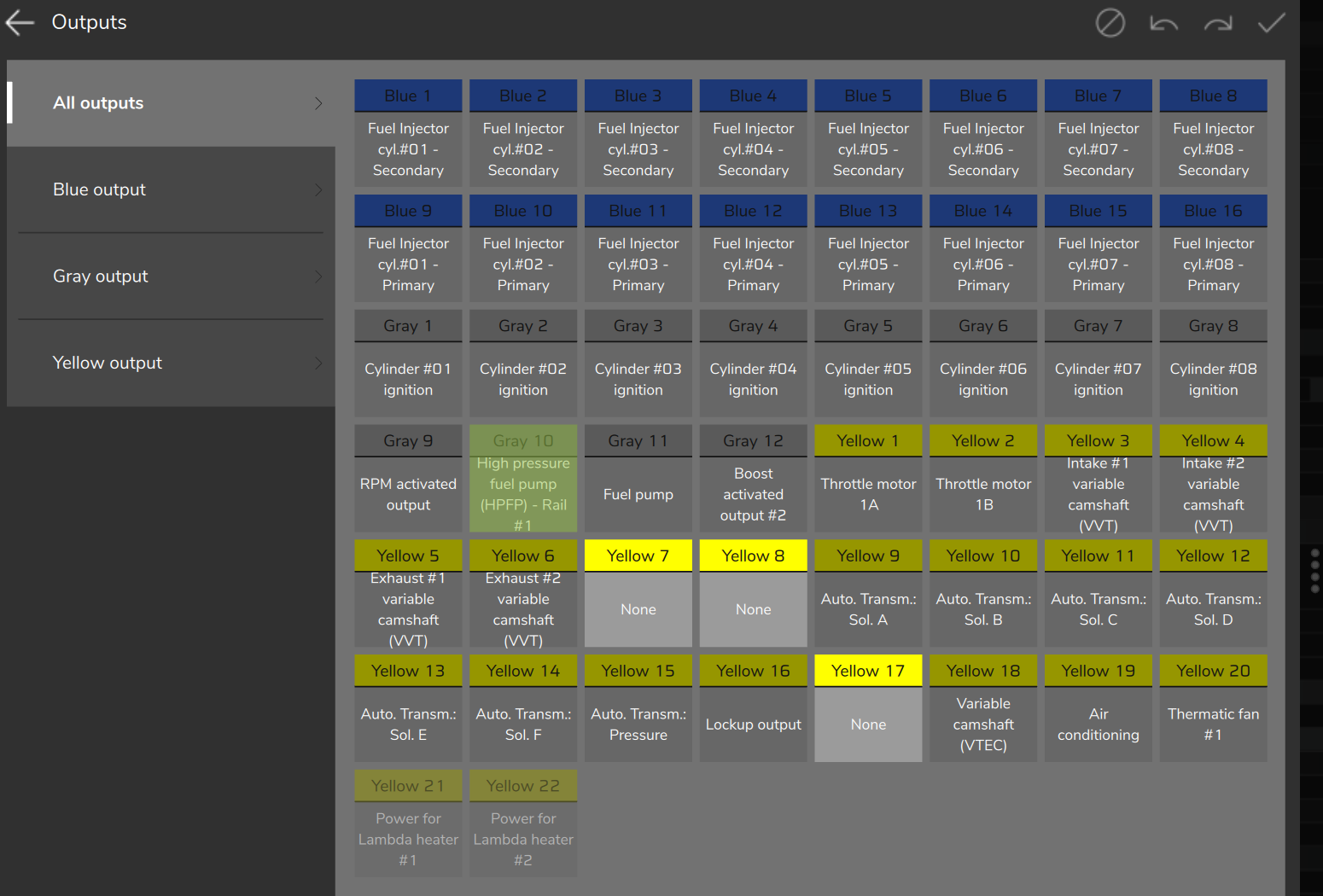
The Output (Rail #2) button only appears with Rails count set to Dual rail.
#What the valve receives
The pump control valve receives one pulse per lobe.
It is not PWM: the function does not control the valve current, and there is no peak or hold current.
Everything between the output and the valve must accept this command: a single pulse per lobe, with no current profile.
The Output behavior field sets the polarity:
- Normal: the output is off at rest and the pulse turns it on. The pump delivers with the valve energized.
- Inverted: the output is on at rest and the pulse turns it off. The pump delivers with the valve off.
Choose according to your valve. The effect on delivery is in How the pump delivers fuel.
During cranking, with feed-forward on, the output stays in the delivery state continuously, for up to the Lockout timeout (from start of cranking) (default 5 s). In the field name, lockout means the injector lockout during cranking, and cranking means turning the engine over with the starter. See Cranking and protections.
#The rail pressure sensor
#Input and sensor table
Rail #1 reads the sensor on input DI1 and Rail #2 on input DI2.
This is the default of the Rail pressure sensor reference field, which has the options HP Rail #1 (DI1) and HP Rail #2 (DI2).
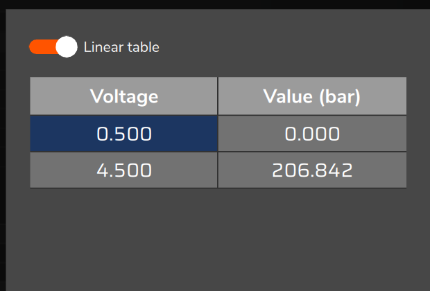
Configure the input in Sensors and calibration > DI rail pressure, on the Pressure sensor DI #1 button (or DI2): choose a Default sensor or build a Linear table, and adjust the Sensor offset if needed.
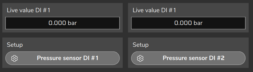
The Linear table accepts 2 to 32 points.
The reading appears in Live value DI #1 (or DI2) and in the DI Rail pressure #1 channel (DI Rail pressure #2 on Rail #2).
#Full scale
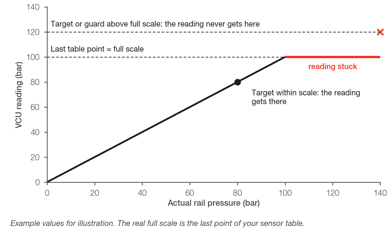
The VCU converts the sensor voltage to pressure through the table, and the conversion clamps at the ends.
Below the first point, the reading stays at the first value. At the last point or above it, it stays at the last value.
That is why the last point of the table is the rail full scale for the VCU. In the Linear table, put the sensor end-of-scale pressure in it; in the Default sensor, check that its end of scale is that of the installed sensor.
Above full scale the VCU no longer sees the pressure, even with the rail rising.
A guard above full scale never acts (except Guard 2 through the target plus 20 bar condition, with the release below full scale), and a target above it is never seen as reached.
Field experience: a reading pinned at a value equal to the last table point, while GDI - Commanded pulse rail 1 changes, indicates a saturated sensor.
#Voltage range
The sensor signal must stay between 0.05 V and 4.95 V.
Below 0.05 V the input is read as shorted. Above 4.95 V, as disconnected.
In both cases the VCU considers the sensor failed. What happens then is in Cranking and protections.
#Pressure basis
The VCU compares the target with the rail sensor reading exactly as the DI Rail pressure #1 channel (or DI Rail pressure #2) shows it.
It does not add or subtract atmospheric pressure.
Enter the target, the guards, the Minimum rail pressure for injection and the Injector cut-off rail pressure limit on the same basis as this reading.
With the key on and the engine stopped, the reading must be stable, at low-side pressure (the lift pump pressure), and the GDI - Rail 1 sensor fault channel must be 0.
If the reading at standstill is shifted, correct it with the Sensor offset.
#The direct injection banks
Each rail has the Feeds bank A, Feeds bank B and Feeds bank C switches.
They tell the VCU which injectors that rail feeds. The marking has two effects:
- The injector cut (during cranking and by low pressure) acts on the marked banks.
- The consumption that feeds the feed-forward comes from the marked banks.
Mark only the direct injection banks. The port injection bank must not be marked: it would be cut along with them and would enter the consumption calculation.
Do not mark the same bank on both rails. FuelTech Vision shows an error: with both marked, the cut of either rail zeroes its pulse.
On an active rail with no bank marked, the injector cut of that rail has no effect, and FuelTech Vision warns you; with no bank marked on any rail, the feed-forward also has no volume.
Adjust the Primary injector rated pressure for bank A (and for banks B and C). The default is 3 bar.
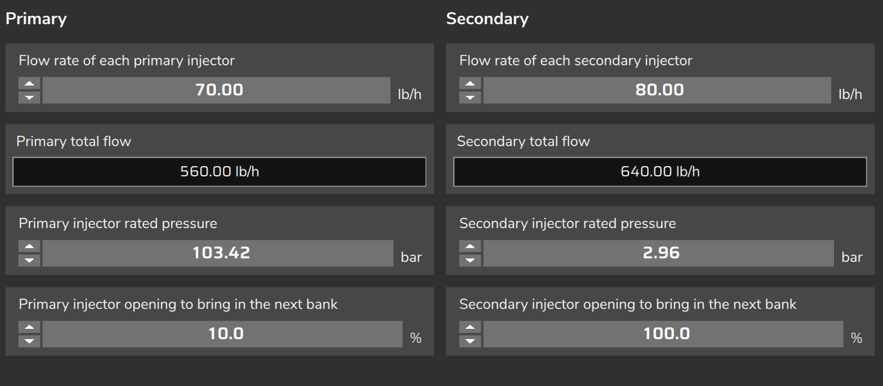
FuelTech Vision warns you when no enabled bank has a direct injection rated pressure, that is, 20 bar or more.
With the wrong rated pressure, the dead time, the effective flow and the differential pressure compensation come out wrong.
The injector dead time table uses the low fuel pressure minus the MAP. It does not use the rail pressure.
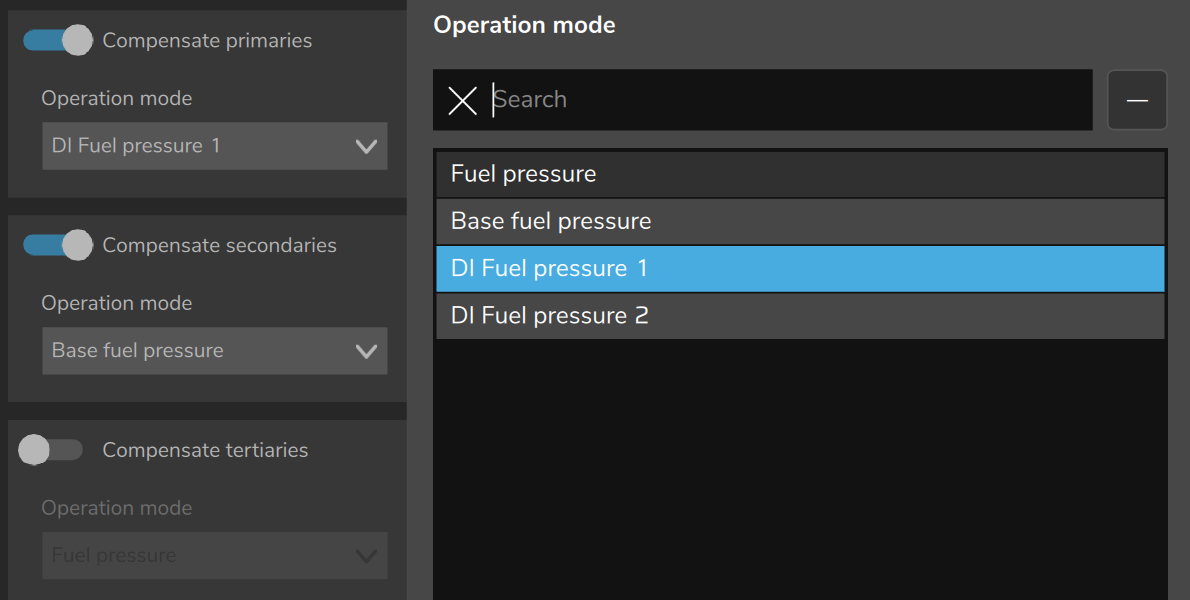
If you use the Differential fuel pressure deviation compensation (Compensate primaries, secondaries or tertiaries), the bank Operation mode must be the pressure of the rail sensor that feeds it: DI Fuel pressure 1 for sensor DI1, DI Fuel pressure 2 for sensor DI2. With any other option FuelTech Vision warns you.
The pump rules only run with the function on: FuelTech Vision shows the list of errors and warnings when you open the map and when you confirm the function. The list does not stop you from writing the map: read it before you start the engine.

#Sync: the phase sensor is mandatory
The function requires a phase sensor, in addition to the crankshaft wheel.
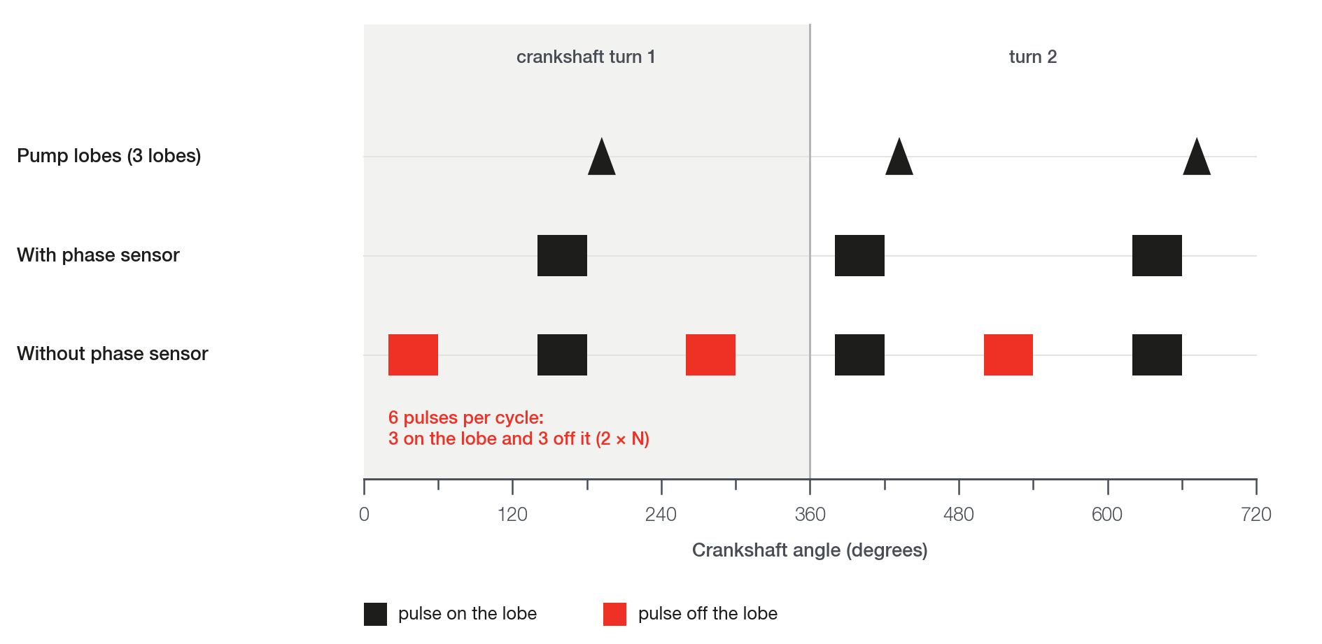
With a phase sensor, the VCU schedules the whole 720 crankshaft degree cycle.
Without it the VCU repeats the pump schedule every crankshaft turn, and half of the pulses fall outside the lobes.
For any number N of lobes there are 2 × N pulses per cycle: N on the lobes and N off them.
Example with 3 lobes and pulse end at 180 crankshaft degrees: the correct pulses end at 180, 420 and 660, and the VCU also fires with the end at 60, 300 and 540.
The valve is only driven after the VCU synchronizes the engine (with a phase sensor, after confirming the phase).
Until then the published RPM is 0 and the pump sees the engine as stopped.
Check that the Engine Sync channel goes to 1 while cranking.
With the function on the VCU ignores Quick start (emulated cam sync), and FuelTech Vision warns you.
The pump angles depend on the Crank index position (an adjustment of the RPM signal: the tooth over the sensor with cylinder 1 at TDC). Check it with a timing light before calibrating (recommended practice). See The lobe angles.
#VVT and cam dependence
The Cam dependence field makes the pump window follow the deviation of the chosen cam.
The options are None, Intake #1, Intake #2, Exhaust #1 and Exhaust #2 (these are the names the screen shows).
Use it only if the pump is driven by a camshaft with a phaser (VVT) and the deviation of that cam is valid. Without VVT, leave None.
The deviation is only published when the Variable camshaft (VVT) function is enabled, the cam sensor is reading and the VVT is acting (after the initial delay and the VVT minimum temperature).
Before turning the dependence on, record a log with the Intake cam position #1 channel (or that of the chosen cam) and check the cam deviation.
Despite the name, this channel shows the deviation, not the position.
How the window follows the deviation is in The lobe angles.
#What requires restarting the VCU
Some fields are only read when the VCU powers up. If you change one of them and do not restart, the VCU keeps the old value.
The VCU does not ask for the restart. After writing the map, power-cycle the VCU (turn it off and back on) with the engine stopped.
| Field | After writing the map |
|---|---|
| Output (Rail #1) and Output (Rail #2) | Restart the VCU |
| Output behavior | Restart the VCU |
| Rail pressure sensor reference | Restart the VCU |
| Rails count | Restart the VCU |
| Turning the function on or off | The VCU restarts by itself, with the engine stopped |
The other fields take effect live, with the VCU connected, except Fuel pressure target map, Crank out RPM and Engine running RPM (disengages lockout), which only take effect when you write the map. See Parameter reference.
#When a part or an adjustment is missing
The configuration is accepted without the items below: check each one before the first start.
| Item | Without it | How to check |
|---|---|---|
| Rail output assigned | The function does not start and no pump channel moves. With 2 rails, the missing output of one rail takes down both. | Output (Rail #1) and, with 2 rails, Output (Rail #2) |
| Rail sensor with a valid signal | After about 0.5 s the VCU enters safe mode (limp-home) and shows the GDI: rail pressure sensor fault alert. Without feed-forward, the pump shuts off. | GDI - Rail 1 sensor fault at 0 with the key on |
| Phase sensor | Half of the pulses fall outside the lobes. | Installed before any pump adjustment |
| VVT acting, with Cam dependence on | The cam deviation may not be getting published. | Log of Intake cam position #1 (or of the chosen cam) |
| Bank marked on the rail | Injector cut of the rail has no effect; with no bank on any rail, feed-forward has no volume. | Warning in the map diagnostic list |
| Target and gains filled in | On a new map they come zeroed, along with the Capture curve G(W): after cranking the duty stays at 0. | Step 4 of Commissioning and tuning step by step |
#FT700 and FT470
The function exists on both VCUs, with the same screens and the same fields.
On the FT470 the 20 outputs are Flex IO: each pin is an output or an input.
The pump pin must be set as an output. The Change for input button switches the pin to an input: do not use it on the pump pin.
A pin used as the pump output cannot also be the rail sensor input.
On a new FT470 map the datalogger does not record the pump channels or DI Rail pressure #1 and DI Rail pressure #2. See Reading the log.
#Checklist before the first start
- Phase sensor installed; Engine Sync at 1 while cranking.
- Crank index position checked with a timing light.
- Electrical choice of the output checked in the manuals; Output (Rail #1) assigned (and Output (Rail #2) with 2 rails).
- Output behavior chosen according to the valve.
- Map written and VCU restarted after changing output, behavior, sensor or rails count.
- Correct Rail pressure sensor reference for each rail; input configured in Sensors and calibration > DI rail pressure.
- Last point of the sensor table (Linear table or Default sensor) equal to the end of scale of the installed sensor; signal between 0.05 V and 4.95 V over the whole range.
- Key on, engine stopped: stable reading at low-side pressure and GDI - Rail 1 sensor fault at 0.
- Maximum target, Guard 1: entry-level, Guard 2: latch level and Guard 2: release level (hysteresis) below full scale, the release below the latch, all on the basis of the sensor reading.
- Only direct injection banks marked, none on both rails; Primary injector rated pressure for bank A (and B, C) adjusted.
- Without VVT, Cam dependence at None. With VVT, the cam deviation logged and checked.
- With the low pressure cut on, the Injector cut-off rail pressure limit plus 2 bar sits below the pressure the pump reaches during cranking, the lowest operating pressure and the lowest target. See Cranking and protections.
- Before the engine runs beyond cranking: provisional target and initial gains entered (the new map comes zeroed); the Capture curve G(W) can start at zero. See Commissioning and tuning step by step.
- Function on and the map diagnostic list with no pump error or warning.
- Pump channels recording in the datalogger (on the FT470, check Record).