7. Feed-forward (physical model) and trim
#What the feed-forward is for
With Enable feedforward (PID as trim) on, the VCU calculates the pump valve pulse from what the injectors are consuming.
The PID no longer commands the whole pulse. It becomes a trim: a limited correction, in ms, added to what the model calculated.
With the model right, it does the bulk of the work and the trim stays near zero.
A trim away from zero for a long time usually means a wrong model: fix the model before touching the gains.
Without feed-forward the PID commands the whole pulse: see Closed loop and PID.
The cranking routine, the injector lockout and the sensor safe mode exist only with feed-forward on: see Cranking and protections.
The feed-forward fields remain editable with it off, but have no effect.
#Where the fields are
On the PC, the PID settings page gathers the Feedforward (physical model), Pump model, PID (shared between the rails) and Transient and trim groups.
Three chart pages belong to the feed-forward: Capture curve G(W), Battery voltage based dead time and Fill factor (RPM).
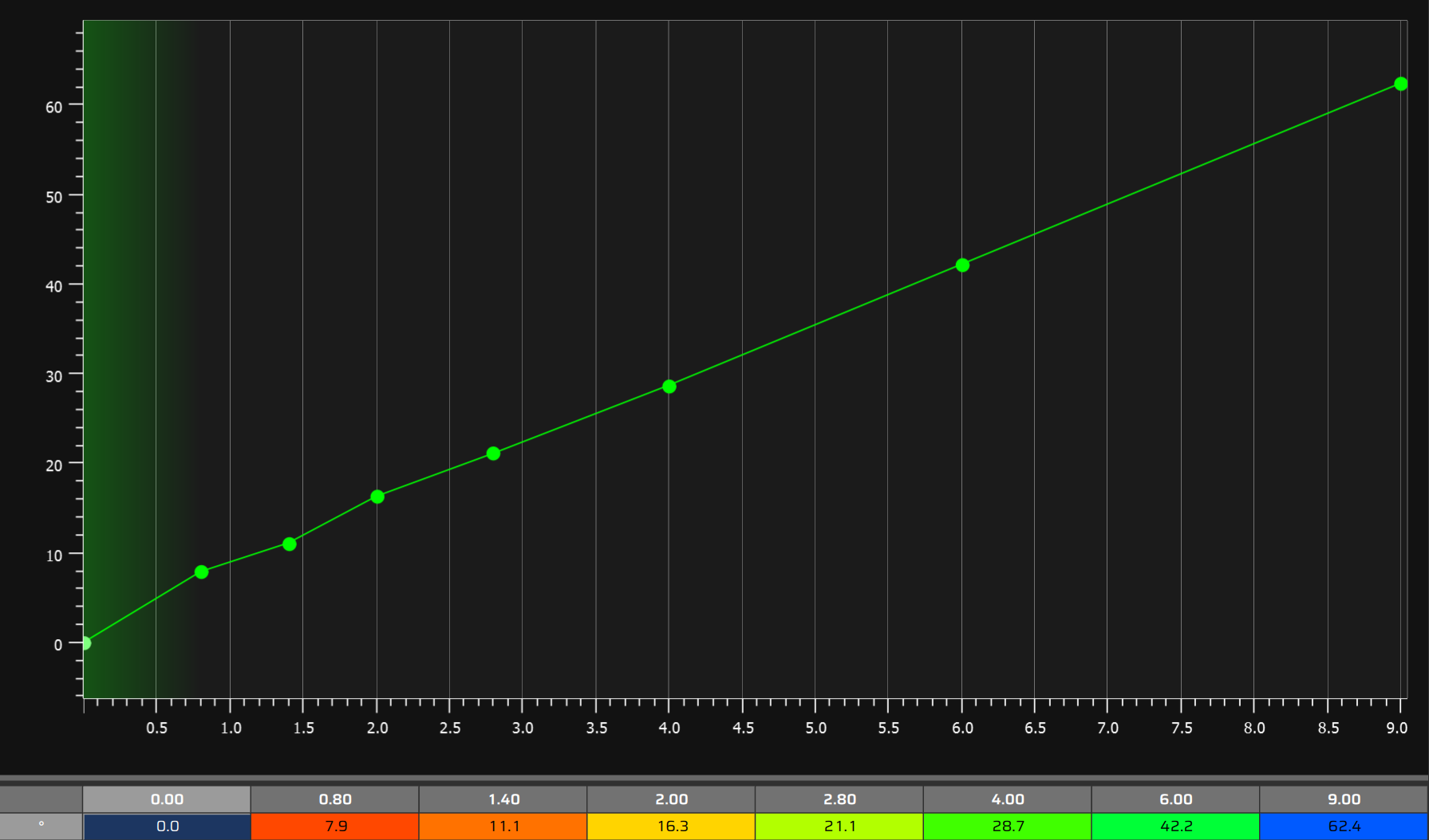
The banks are in General settings, in the Rail #1 group (and Rail #2).
On the phone and on the panels the fields are the same, on pages without the group titles.
Pump model is only a group title: it gathers Valve base dead time (t0), Leakage coefficient (beta), Angled window upper limit and Valve delay (phase advance).
There is no pump list and no preset: all values come from calibration.
#The command calculation
The VCU calculates the useful part of the pulse from the model, adds the trim and the valve dead time, and limits the result with two limits.
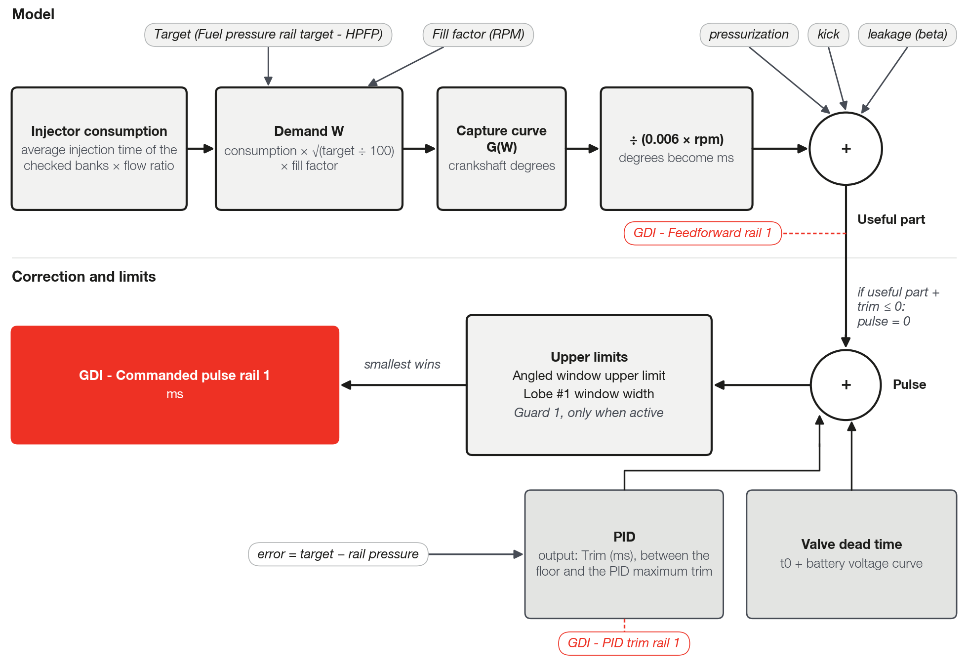
useful part = G(W) ÷ (0.006 × rpm) + leakage + kick + pressurization   [ms]
pulse       = useful part + trim + valve dead time                      [ms]
pulse = 0   when useful part + trim ≤ 0
final pulse = the smaller of pulse, angular limit and window width (in ms)
The factor 0.006 × rpm converts crankshaft degrees into ms: at 3000 rpm, each ms is equal to 18 crankshaft degrees.
Each term is explained below, in the order of the calculation.
The two limits are the Angled window upper limit and the width of the lobe #1 window. The trim stays between the floor and the PID maximum trim.
GDI - Feedforward rail 1 shows the whole useful part, with leakage, kick and pressurization, without dead time and without trim.
Log check: with a pulse above zero and no limit acting, GDI - Commanded pulse rail 1 equals GDI - Feedforward rail 1 plus GDI - PID trim rail 1 plus the valve dead time (t0 plus the battery curve, at the voltage of the moment).
Each channel exists for both rails: replace 1 with 2.
#Injector consumption
The consumption is the average of the injection time of the banks checked in Feeds bank A / B / C, in the active rails.
It is an average, not a sum.
The injection time already includes the injector dead time and the corrections applied to the pulse. Do not confuse it with the pump valve dead time.
The consumption is filtered, with a constant of 0.3 s: it follows the engine with a small delay.
The total injection cut of the bank (not the partial one), including the low pressure cut, sets the injection time to zero: the consumption drops and the feed-forward shrinks with it.
Mark only direct injection banks. A bank that is marked but disabled in injection is ignored. See Before you start: installation.
If the injectors are not the ones of the calibration, the VCU corrects the consumption by the ratio of the flows:
consumption = average injection time of the checked banks
              × (flow of the installed injector ÷ flow of the reference injector)
Fill in Injector rated flow (the installed injector) and Injector rated flow preset reference, in lb/h.
The reference is the flow of the injector with which the G(W) was built. The label mentions preset, but there is no preset.
Enter both in the same unit and at the same nominal pressure: the VCU only divides one by the other.
With either one at 0, the ratio is 1.
If you built the G(W) with the installed injectors: write the same value in both fields.
If you changed the injectors afterwards: keep the reference and update only the installed one.
#Demand W and fill factor
W = consumption × √(target ÷ 100) × fill factorW has no unit on the screen. It is the consumption in ms corrected to 100 bar: with a target of 100 bar and Fill factor (RPM) at 1.00, W equals the consumption.
The target is the one of the Fuel pressure rail target - HPFP channel (already smoothed), on the same reading basis as DI Rail pressure #1.
W is the axis of the Capture curve G(W). The log has no W channel: to know which point of the curve is in use, calculate W with the formula above, from the injection time of the checked bank and the target.
The Fill factor (RPM) is an 8-point curve by rpm, from 0.50 to 1.20, with default 1.00 (no effect).
It multiplies W before the G(W): raising the factor at an rpm makes the VCU read the curve at a higher W at that rpm.
Recommended practice: leave it at 1.00 until, with the G(W) right, the trim shows a trend with rpm. Then adjust one rpm band at a time and check in the log.
#Capture curve G(W)
The G(W) tells how many crankshaft degrees of useful pulse the pump needs to deliver the demand W.
It is a duration, not a position. Do not confuse it with Lobe #1 closing angle, which marks where the pulse ends.
The VCU converts the degrees into ms with 0.006 × rpm: the same angle becomes a shorter pulse when rpm goes up.
An angle of 30 crankshaft degrees is 1.67 ms at 3000 rpm and 0.83 ms at 6000 rpm.
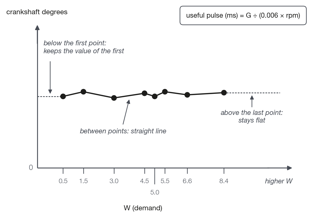
The W axis goes from 0 to 20 and the data, from 0 to 180 crankshaft degrees. The curve has up to 8 points.
By default, the axis is 0.5 / 1.5 / 3.0 / 4.5 / 5.0 / 5.5 / 6.6 / 8.4 and all the data are 0.
Between two points the VCU interpolates in a straight line.
Beyond the ends it keeps the value of the end: below the first point the curve does not drop to zero, and above the last it stays flat.
A curve at zero means no volume from the model.
Keep the axis in increasing order of W: an out-of-order curve gives meaningless interpolation.
#Valve dead time
The valve dead time is the part of the pulse that delivers no volume.
It is the sum of the Valve base dead time (t0) (0 to 5 ms, default 1.5 ms) with the Battery voltage based dead time curve.
The curve has 6 voltage points (default 6 to 16 V, data at 0) and adds −5 ms to +5 ms to t0.
Keep the sum positive over the whole voltage range: the VCU does not limit this value from below.
The dead time only enters when there is demand: if useful part + trim ≤ 0, the pulse is zero, without dead time.
For this reason there is no minimum pulse: the pulse is zero or greater than the dead time, except when a limit cuts it.
In degrees, the dead time grows with rpm: 1.5 ms is 9 crankshaft degrees at 1000 rpm, 27° at 3000 rpm and 54° at 6000 rpm.
Recommended practice: adjust t0 last and alone, because it changes the trim that was used to build the G(W).
#Leakage, kick, pressurization and delay
Four small terms complete the model. All of them apply to both rails.
| Field | What it adds to the pulse | When it acts | Default |
|---|---|---|---|
| Leakage coefficient (beta) | beta × (target ÷ 100) × (1000 ÷ rpm), in ms | Always. Grows with the target and falls with rpm. | 0 |
| Fuel enrichment gain (kick) and Kick upper limit | gain × (consumption rise in ms/s − 2.5), between 0 and the limit | Only with consumption above 0.3 ms and a rise above 2.5 ms/s. Only adds. | gain 0.03; limit 1.5 ms |
| Pressurization gain (ms/(bar/s)) | gain × change in the target in bar/s, between −1.5 and +1.5 ms | Target rising adds, target falling subtracts. | 0.003 |
| Valve delay (phase advance) | Nothing in the duration: advances the whole pulse by 0.006 × rpm × delay, in crankshaft degrees | Always | 0 ms |
Leave the Leakage coefficient (beta) at 0 without a measurement.
The kick reinforces the fast rise of consumption. The fall of consumption is the job of the deceleration cut, and the fall of the target is the job of pressurization.
With the default gain of 0.003, a target rise of 100 bar/s adds 0.3 ms. The target used is already smoothed: see Pressure target.
The effect of the Valve delay (phase advance) on the position of the pulse is in The lobe angles.
#Trim and its limits
The trim is the PID output, in ms. It stays between a floor and the PID maximum trim.
The defaults are PID minimum trim of −2 ms, PID maximum trim of +2 ms and Trim floor: feedforward fraction of 50 %.
trim floor = −the larger of the absolute value of Minimum trim and (Trim floor × useful part)   [ms]
trim       = PID output, limited between the floor and the Maximum trim                         [ms]
With the defaults and a useful part of 6 ms, the floor is −3 ms (50 % of 6 is larger than 2). With a useful part of 3 ms, the floor is −2 ms.
The floor follows the feed-forward: at high demand the trim can take away more, at low demand the PID minimum trim applies. With Trim floor: feedforward fraction at 0 %, only the PID minimum trim applies.
The trim can take away the whole useful part. When useful part + trim reaches zero or less, the pulse is zero.
GDI - Trim at limit rail 1 lights when the PID output was cut by the floor or by the PID maximum trim at that instant.
Trim at limit for a good part of the time usually means a wrong model. Recommended practice: fill in the G(W) and only then open the PID maximum trim.
Trim at limit is followed through the channel, with no alert on the screen.
The limit of the integral term and the gains are in Closed loop and PID.
#Pulse limits
After the sum, the pulse goes through two limits and the smaller one applies.
The Angled window upper limit (10 to 180 crankshaft degrees, default 60°) limits the duration of the pulse and counts the valve dead time.
The other is the width of the lobe #1 window, closing minus opening (default 120 crankshaft degrees): see The lobe angles.
The limit in ms is the degrees ÷ (0.006 × rpm): 60° is 3.33 ms at 3000 rpm and 1.67 ms at 6000 rpm; 120° is 6.67 ms and 3.33 ms.
With the defaults, the duty stops at 50 %, even with higher demand.
The duty is the pulse divided by the time of the window width. Compare maps by GDI - Commanded pulse rail 1, in ms.
An Angled window upper limit larger than the window width has no effect.
An Angled window upper limit smaller than the dead time in degrees, at high rpm, cuts the pulse inside the dead time: no useful part is left.
When widening the window, review the Angled window upper limit together: with the default of 60°, the pulse stays held at 60 crankshaft degrees.
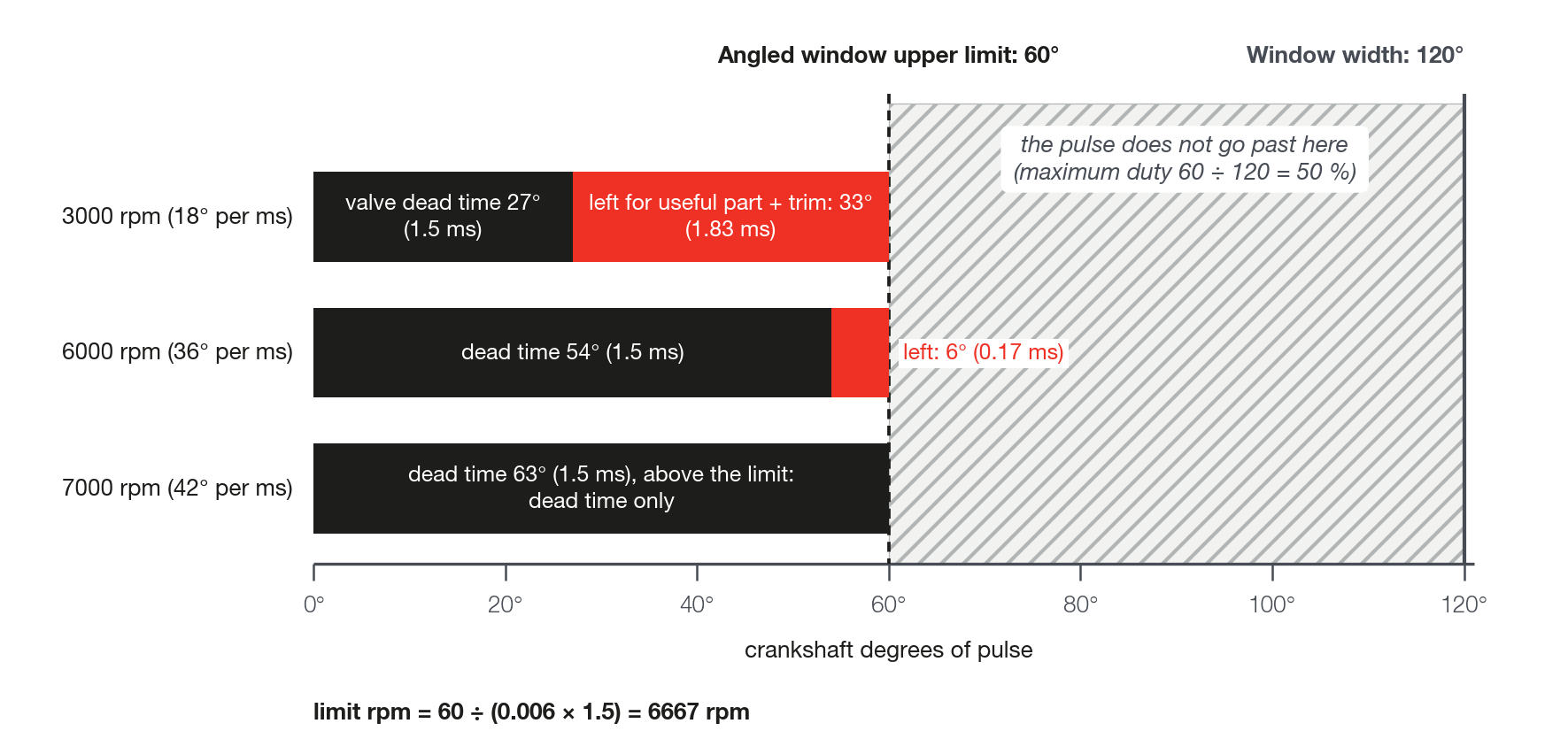
The rpm from which only dead time is left in the pulse is:
rpm = angular limit ÷ (0.006 × valve dead time)With 60° and 1.5 ms, it is 6667 rpm.
If a limit holds the pulse and the rail is below the target, it is a configuration limit, not a model limit.
GDI - Angular upper limit (max Theta) rail 1, GDI - Lobe window upper limit rail 1, GDI - Trim at limit rail 1 and GDI - Guard 1 trimming rail 1 tell which limit is holding the command.
See Diagnostics: symptoms and causes and, for Guard 1, Cranking and protections.
#Zero pulse
Outside cranking and the protections, the pulse goes to zero in two cases. There is no zero pulse flag: the signal is GDI - Commanded pulse rail 1 equal to zero, and GDI - Trim at limit rail 1 may be at 1 at the same time.
- Useful part + trim ≤ 0: the consumption is zero or the trim took away the whole useful part.
- Deceleration cut: filtered consumption below 0.3 ms and pressure more than 10 bar above the target.
The pump only puts fuel into the rail. For the pressure to fall, the rail needs consumption.
Entry into the deceleration cut takes up to about 1 s after the injectors are cut, because of the consumption filter (estimate).
#How to build the G(W) and the fill factor
Recommended practice, with the reason for each step.
- Stabilize the loop first, with initial gains and no cycling in the rail (see Commissioning and tuning step by step). The trim only teaches the curve if the loop does not oscillate.
- Start with the curve at zero or modest, with low angles, and let the trim show how much is missing. The G(W) belongs to the car: do not use the curve of another engine.
- Record a steady-state log, with GDI - Feedforward rail 1, GDI - PID trim rail 1, GDI - Commanded pulse rail 1, GDI - Pressure error rail 1, the four limit flags and the injection time of the checked bank.
- Calculate W only from the steady-state samples: the VCU uses filtered consumption and a smoothed target, and outside steady state the calculated W falls at the wrong point of the curve. Group by W band and by rpm band.
- Use only samples with a commanded pulse above zero: a zero pulse is a cut, not noise.
- In each band, the median trim shows the error of the curve. Positive trim means the curve delivers too little. Change the data of the point: new G = G + trim (ms) × 0.006 × rpm of the band.
- Example calculation: a median trim of +0.5 ms at 3000 rpm asks for +9 crankshaft degrees (0.5 × 18).
- Extend the W axis up to the largest W in the log. Above the last point the curve stays flat, and all the error goes to the trim.
- Repeat until the median trim stops changing, with the goal of staying within ±0.25 ms per rpm band (field experience). The trend that is left with rpm is for the next step.
- If the trim still shows a trend with rpm, adjust the Fill factor (RPM). Only then adjust t0, alone.
#Two rails
The feed-forward parameters and the three curves are common to both rails. Only the trim belongs to each rail.
The consumption is a single average of the banks checked in both rails: both rails receive the same useful part.
If one rail always asks for more trim than the other, the split of the banks between the rails is not the cause: it does not change the feed-forward.
Accept the difference: it is the trim correcting the asymmetry.