5. Before you start: engine, fuel, injectors and sensors
The VE table holds only the engine's filling. Displacement, fuel, injectors and sensors enter the calculation outside it, and the VCU trusts what you enter.
If any of these inputs is wrong, the O2 sensor shows the error, the correction ends up in the VE and the VE no longer represents the engine. Check everything in this chapter before tuning the VE.
The menu paths in this chapter are those of FuelTech Vision on the computer.
#Fuel strategy
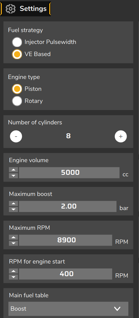
In Engine Settings > Engine settings, the Fuel strategy field has two options: Injector Pulsewidth, where the table holds milliseconds, and VE Based, where the table holds the engine filling in % and the VCU calculates the milliseconds.
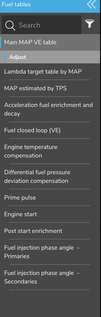
With VE Based, the Fuel tables menu shows Main MAP VE table, Lambda target table by MAP, Acceleration fuel enrichment and decay and Fuel closed loop (VE), plus MAP estimated by TPS while the MAP failsafe is set to MAP estimated by TPS table (the default), and hides the pulsewidth-mode tables and the compensations that exist only in that mode.
Changing the strategy does not convert any table: what happens to the tables and the functions of each mode, and how to migrate a map or create a new VE map with the base map wizard, is in From the pulsewidth map to VE.
The strategy does not change with the VCU live: it takes effect when the map is written to the VCU. After writing, check in the log that the VE channels, such as VE - Efficiency %, show a value; if they do not, power-cycle the VCU (turn it off and on).
#Engine
In Engine settings, Engine volume is the total displacement, in cc, CI or L, and Number of cylinders divides that volume: the calculation uses the volume of one cylinder.
A new map starts with volume 0 and 8 cylinders: fill in both. With volume at zero the bank does not inject in VE mode and FuelTech Vision shows VE mode active, but the engine volume (displacement) is zero.
Maximum boost serves the base map wizard, and Maximum RPM limits the rev limiter (RPM cut) and the LED tables: neither changes the fuel in VE mode.
Main fuel table (TPS or Boost) also changes nothing in VE: the VE tables are always RPM by MAP.
#Fuel
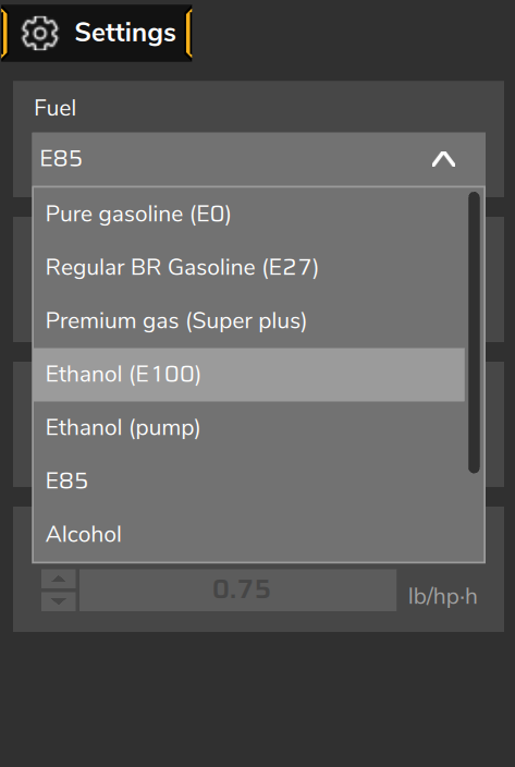
In Engine Settings > Fuel configuration, the Fuel field defines the stoichiometric AFR that the VCU uses to go from air mass to fuel mass.
| Fuel | Stoichiometric AFR | Density (g/cm³) |
|---|---|---|
| Pure gasoline (E0) | 14.7 | 0.745 |
| Regular BR Gasoline (E27) | 12.6 | 0.750 |
| Premium gas (Super plus) | 13.5 | 0.745 |
| Ethanol (E100) | 9.0 | 0.789 |
| Ethanol (pump) | 8.4 | 0.809 |
| E85 | 9.8 | 0.780 |
| Methanol (the screen shows Alcohol) | 6.5 | 0.792 |
| Diesel S10 | 14.5 | 0.840 |
| Custom | typed in | typed in |
The density does not enter the injection time. It only enters the estimated fuel consumption, flow, power and torque channels, and the conversion of injector flow between cc/min and lb/h.
AFR, density and BSFC (brake specific fuel consumption, which is only used to estimate power and torque in the log) are editable only in Custom.
The fuel also defines the scale between lambda and AFR throughout the interface: changing the fuel changes the AFR shown, not the lambda stored in the tables.
#Pump gasoline in Brazil: E27 or E30
The Regular BR Gasoline (E27) preset, the Brazilian regular gasoline, uses stoichiometric AFR 12.6. In Brazil, pump gasoline today has 30% ethanol (E30), and its stoichiometric AFR differs from the preset by a few percent.
With Brazilian gasoline, use the preset and keep the same one from the start to the end of the tune. The calculated fuel is inversely proportional to the AFR: this difference shows up as a few percent more or less in the table's VE, and the VE tune and the closed loop absorb it. With another gasoline, choose in the table above the fuel you actually use (with no ethanol, Pure gasoline (E0)) or Custom with its stoichiometric AFR (see the warning above), and keep it from start to end as well.
#Flex Fuel in VE mode
With the ethanol sensor set up in Sensors and calibration > Flex fuel and the Flex fuel function in Other Functions enabled, the VCU stops using the fuel chosen in Fuel configuration and calculates with the blend that the sensor reads.
The blend runs from pure gasoline (AFR 14.7) to anhydrous ethanol (AFR 9.0), fixed endpoints in FuelTech Vision. The blend AFR is the harmonic mean of the two, weighted by ethanol content, the physically correct calculation, because what adds up is fuel mass per air mass:
1 ÷ blend AFR = (1 − E) ÷ 14.7 + E ÷ 9.0
E = ethanol content read by the sensor, from 0 to 1
Result: E27 gives 12.55; E50, 11.16; E85, 9.56; E100, 9.00. The density and BSFC of the blend vary in a straight line between the two endpoints.
The lambda target receives the offset from the O2 closed loop target compensation table (MAP), pressure by ethanol content. By default it adds 0.010 at E0 and subtracts 0.040 at E100. The VE - O2 closed loop target channel shows the target already offset.
The Acceleration fuel enrichment compensation and the Engine start and Prime pulse compensation also act in VE: see Enrichments and compensations in VE mode.
The Main fuel injection compensation tables (MAP and TPS versions) and the O2 closed loop target compensation table (TPS version) do not act in VE: in VE, the fuel change and the MAP target table take their place.
The Main ignition compensation tables (MAP and TPS versions) of Flex fuel do not act in VE mode either: the ignition timing receives no correction for ethanol content.
With an invalid sensor, the VCU uses Default blend in case of error on flex fuel sensor, 50% by default, which gives AFR 11.16. On a car running pure gasoline that is about 32% more fuel than needed: set the value to the fuel the car uses.
With hydrous ethanol in the tank the blend does not reach its AFR (8.4): with the sensor reading about 95%, the VCU calculates with 9.18 and the mixture comes out about 9% lean. FuelTech Vision warns about it.
With Flex fuel active, work in lambda: the AFR the screen shows uses the configured fuel, not the blend read by the sensor.
The FlexFuel - Fuel injection compensation channel shows how much more fuel the blend asks for than the configured fuel: from Regular BR Gasoline (E27) to E100, 40% more.
#Injectors
The injector data is in Engine Settings > Injector configuration. The banks and modes are in Engine Settings > Fuel injection.
#Rated flow
Flow rate of each primary injector is the flow of one injector, not of the bank. A new map starts with 230 lb/h: change it to that of your injector.
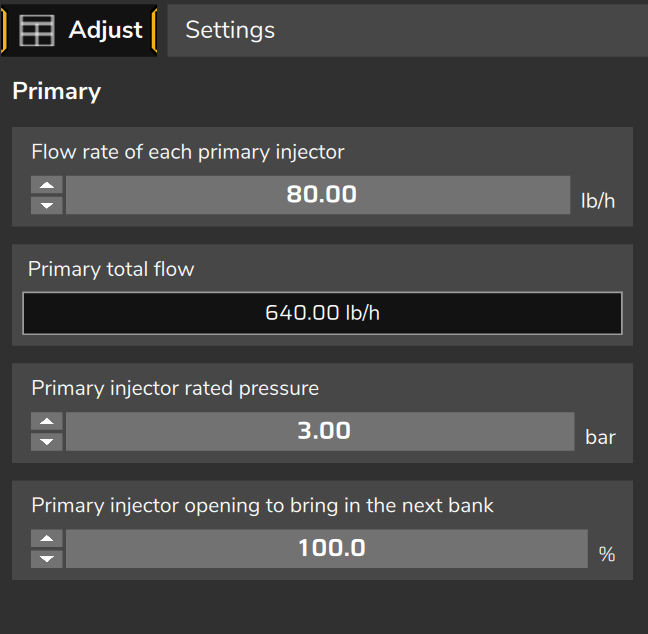
The VCU works with mass flow; the screen shows it in the unit you choose, such as lb/h, cc/min, L/h or g/s. Zero flow leaves the bank with no injection in VE mode.
Primary total flow, read-only, is the flow times the number of cylinders. It serves the estimated consumption, not the injection time.
When you type in cc/min, FuelTech Vision converts to mass using the density of the fuel selected at that moment. Choose the fuel before typing the flow; the most accurate flow is the one measured with the car's own fuel.
#Rated pressure: enter the injector at its working pressure
Primary injector rated pressure and the rated flow form a pair: the flow the injector delivers at that pressure. A new map starts with 3.00 bar.
The VCU uses this pair to calculate the pulse and corrects it by the square root of the real differential pressure (line minus manifold).
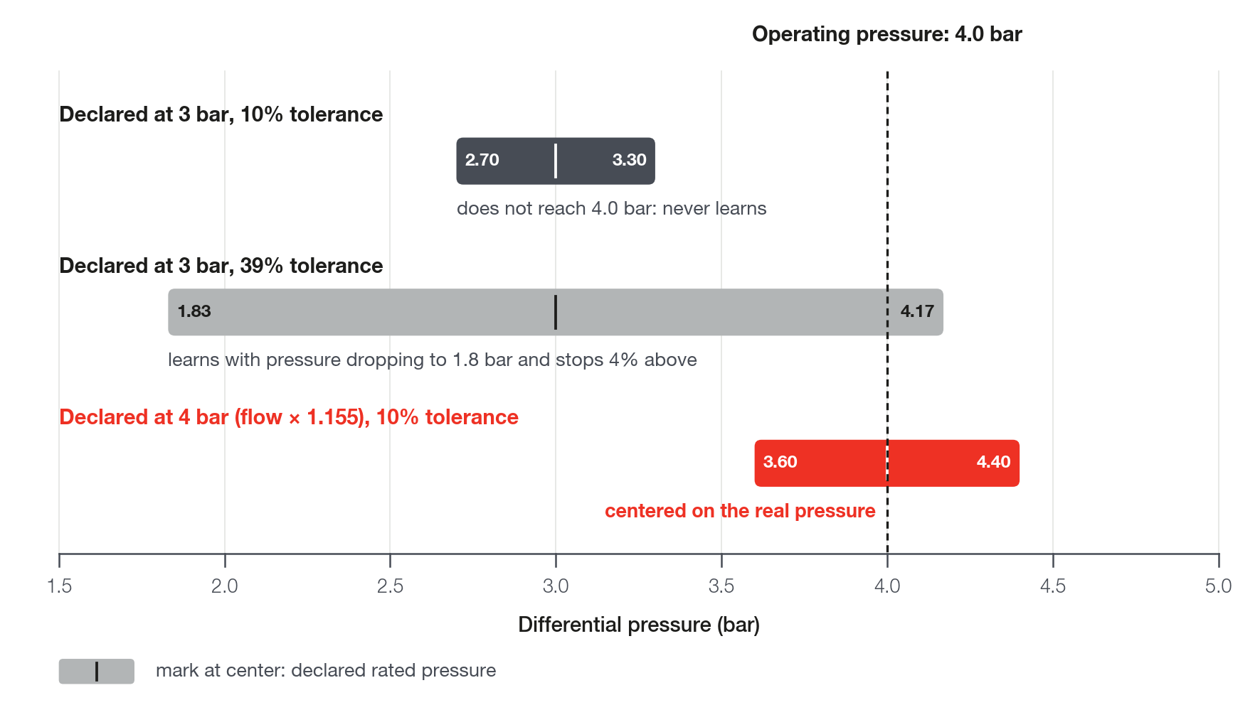
With the fuel pressure sensor in use, the rated pressure is also the center of the window in which learning writes: the differential pressure must stay within 10% of it, the default value of Differential pressure tolerance for learning.
So enter the pair at the differential pressure at which the engine works:
rated pressure = working differential pressure
rated flow     = catalog flow × √(working pressure ÷ catalog pressure)
Example: an 80 lb/h injector measured at 3 bar, on a car with the regulator at 4 bar above the manifold. Enter 4 bar and 80 × 1.155 = 92.4 lb/h (1000 cc/min becomes 1155 cc/min). The injection time does not change and learning starts to happen.
If the manufacturer publishes the flow at the pressure at which your engine works, use the published number.
Change both fields together and write the map. The pressure alone leaves the engine about 15% rich; the flow alone, about 13% lean. Compare Injection time A in the log before and after, under the same condition: it must be the same.
Leave the tolerance at 10%: it is not meant to compensate a wrong rated pressure. On a 4 bar car with the injector entered at 3 bar it would need about 40%, and learning would write with the pressure dropping to 1.8 bar.
The working pressure is the differential one, the one in the Differential fuel pressure channel (the screen shows Base fuel pressure). With a manifold-referenced regulator it is the regulator's base pressure. Without that reference it changes with load: use the middle of the range as the rated pressure and increase the tolerance until it covers the ends.
Before changing anything, check the pressure with a gauge on the line. If the sensor and the gauge disagree, fix the sensor calibration, not the rated pressure.
Sign that the rated pressure is far from the working pressure: the VE learning (LTFT) screen shows Differential pressure out of tolerance and the closed loop state in the log is Fuel pressure out of range. The O2 sensor corrects, but nothing is learned.
The base map wizard's injector catalog has injectors with 4 bar and 6.2 bar pressure. If that is not your car's pressure, apply the same calculation.
Pressure drop: the VCU compensates by the square root down to half of the rated pressure. Below that the correction stops at 41% more and never cuts the fuel. With the injector entered at 4 bar the limit is 2 bar; below that the fuel system has already failed.
#Two injectors per cylinder
Two injectors per cylinder that fire together, connected to the same output or with the second on the Fuel Inj. cyl. #01 - Primary. Duplicated output and following ones: in Flow rate of each primary injector, type the sum of the flows of the cylinder's injectors.
The VCU calculates one pulse per cylinder with the entered flow and repeats that pulse, at the same moment, on the Aux output, including in the acceleration fuel enrichment and in the prime pulse at start.
Example: two 80 lb/h injectors per cylinder give 160 lb/h. Typing 80, the engine gets double the fuel: a lambda target of 0.80 becomes about 0.40.
The deadtime remains that of one injector, and the rated pressure is the pressure at which the two had their flow measured. Use identical injectors on the same cylinder.
The Prime pulse is in milliseconds: with two injectors per cylinder it delivers double. Review that table when going from one to two injectors.
A second injector on bank B is a different thing: bank B only comes in when A reaches the configured opening limit. For two injectors firing together from idle, use the Aux output.
In the log and in the Diagnostics Panel, the cylinder's injection time is already that of the two injectors: there is no separate channel for the Aux output.
With Pin assignment mode set to Auto, after changing the number of cylinders or the bank mode, check in the output list that the Aux output is still on the right pin.
#Banks, modes and staging
In Fuel injection, Banks tab, Fuel primary is on by default and banks B and C are off. A bank that is off does not inject.
Primary mode: Multipoint, Semi-sequential (default) or Sequential. On a piston engine, sequential requires a phase sensor (cam sync).
Primary outputs is the number of outputs the bank uses, not the number of injectors.
Primary injector opening to bring in the next bank, which only appears in VE (100% by default), is the injector staging: bank A delivers up to that opening and the rest goes to the next bank that is on.
With all banks at the limit, the missing time is added equally to all of them (see How the VCU calculates fuel in VE mode). A saturated injector, at 100% of the cycle, freezes the closed loop: see VE closed loop.
#Direct injection
The VE calculation knows only one fuel pressure: the differential pressure of the low-pressure line, which is the Fuel pressure sensor minus the MAP, or the failsafe.
The high-pressure rail pressure enters through Fuel tables > Differential fuel pressure deviation compensation, with the function enabled and, per bank, Compensate primaries on and Operation mode set to DI Fuel pressure 1 (or DI 2, depending on the rail sensor).
In VE mode only the DI 1 and DI 2 modes of that screen act: the Fuel pressure and Differential fuel pressure (the screen shows Base fuel pressure) modes are already inside the VE calculation and are ignored.
The bank factor uses the DI Fuel pressure reference (180 bar by default) and the rail reading, limited from below to half the reference:
DI factor = √(DI reference ÷ larger of DI Rail pressure #1 and DI reference ÷ 2)Recipe for an engine with direct injection only, on each direct injection bank:
- Uncheck Use fuel pressure sensor and enter a value in Fuel pressure failsafe, for example 3.00 bar.
- In Primary injector rated pressure, enter the same value as the failsafe.
- In Flow rate of each primary injector, enter the injector data sheet flow multiplied by the square root of (DI reference ÷ data sheet pressure).
- Enable the Differential fuel pressure deviation compensation function and turn on the bank compensation at DI Fuel pressure 1.
Example: injector of 15 g/s at 100 bar (119.05 lb/h) with a 180 bar reference: 119.05 × √1.8 = 159.72 lb/h. With that, the pulse follows the physics from 90 to 250 bar of rail.
Choose the reference at no more than double the lowest rail pressure the engine uses, at idle or on deceleration. Below half the reference the factor stops growing: with a 180 bar reference and the rail at 50 bar, the VCU injects about 25% less than it should.
Do not type the high-pressure injector's pressure into Primary injector rated pressure. With 100 bar entered and the low side at 3 bar, the VCU injects 41% more with the rail at 100 bar and double at 200 bar; with the compensation on and a 180 bar reference, about 90% more with the rail from 90 bar up.
With the high-pressure pump enabled and the recipe above, FuelTech Vision shows the warning that no bank has a direct injection rated pressure (20 bar or more). In VE mode the rated pressure does not enter the deadtime or the direct injection compensation: with this recipe, the warning is expected.
An engine with both direct and port injection: the loop uses the rated pressure of the first bank whose Operation mode is not direct injection, even with the compensation off. Put the direct injection bank on DI Fuel pressure 1 and the port bank on Differential fuel pressure (the screen shows Base fuel pressure).
In that engine the low-side pressure sensor stays in use, and the rated pressure of the direct injection bank must be the differential pressure of the low side. This only works with the low-side regulator referenced to the manifold, which keeps that pressure nearly constant; with the low side at fixed pressure, direct injection enriches with boost (about 12% at +1 bar, with the low side at 5 bar).
The deadtime table uses the differential pressure of the low side: the deadtime of the direct injection injector does not follow the rail pressure.
The direct injection factor does not appear in the log: calculate it with the DI Rail pressure #1 channel using the formula above.
#Deadtime
Primary injectors deadtime is an 8 × 8 table: battery voltage in the columns, differential pressure in the rows, values in ms from 0 to 5 ms, with 3 decimal places.
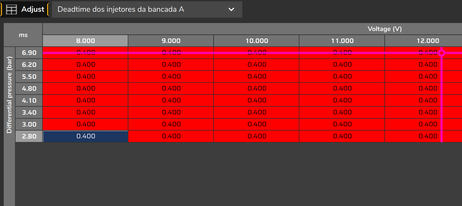
In VE mode the deadtime is absolute: the table value is added to each pulse, after the VE calculation. The Reference deadtime for primaries injectors field exists only in pulsewidth mode.
The table is per bank, not per cylinder.
The VCU reads the point for the current voltage and pressure. On the screen, the cursor shows that point; in the log, the Primary injectors deadtime channel shows the value used.
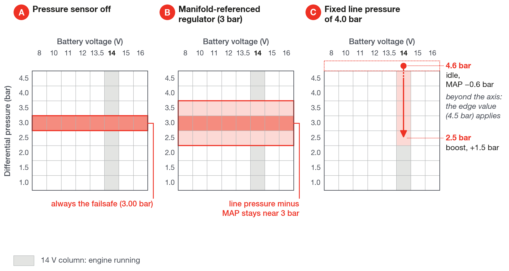
With Use fuel pressure sensor off, the VCU always uses the Fuel pressure failsafe (3.00 bar by default) and reads only that row. On, it uses the line pressure minus the MAP.
Outside the axes the VCU uses the edge, without extrapolating: the pressure axis must cover the pressure at which the engine works. The base map wizard builds the axis from 1.0 to 4.5 bar; with an injector of higher reference pressure, extend the axis.
A new map comes with the table of a generic injector: 1.000 ms at 12 V and 3.0 bar. Replace it with your injector's data. A zeroed table with the bank on generates a warning.
What matters most is the voltage: in the FuelTech Vision generic injector the deadtime falls from 1.00 ms at 12 V to 0.88 ms at 14 V.
#When the manufacturer gives the curve at a single pressure
Copy the values into the voltage columns, interpolating in a straight line between the manufacturer's points, in the row of the curve's pressure.
If the engine's differential pressure does not change (manifold-referenced regulator, or pressure sensor off), repeat the curve in all the rows: the VCU only reads the row for its pressure. The curve must be the one for the pressure at which the engine works.
If the differential pressure varies (line with fixed pressure, not referenced to the manifold), FuelTech Vision uses a generic rule: the deadtime rises 2.8% per bar above the curve's pressure and falls 2.8% per bar below it. It is the rule of the wizard and of the factory table: an estimate, not a measurement of your injector.
By that rule, on a 1 ms deadtime, the pressure changes it by less than 0.03 ms per bar. It is the manufacturer's voltage curve that must be right.
#Short pulse linearization
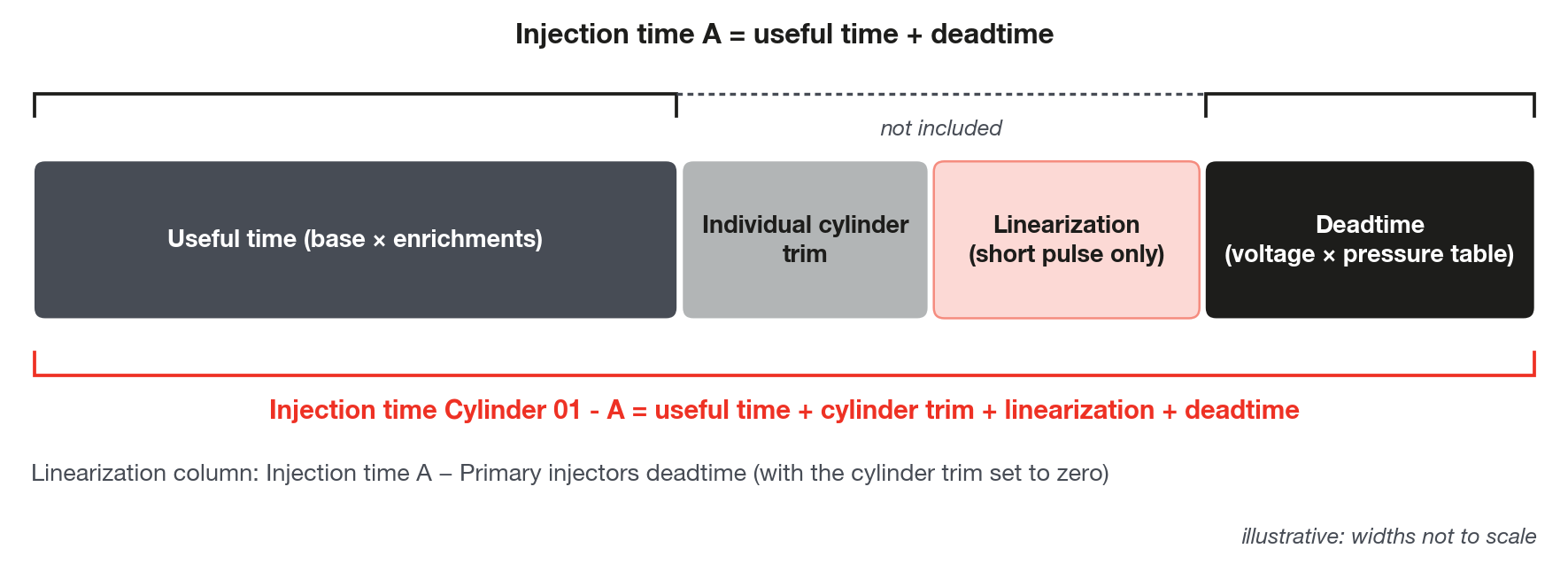
Primary injector linearization is the short pulse adjustment: milliseconds added to the useful time, which is the pulse without the deadtime. A positive value gives more fuel.
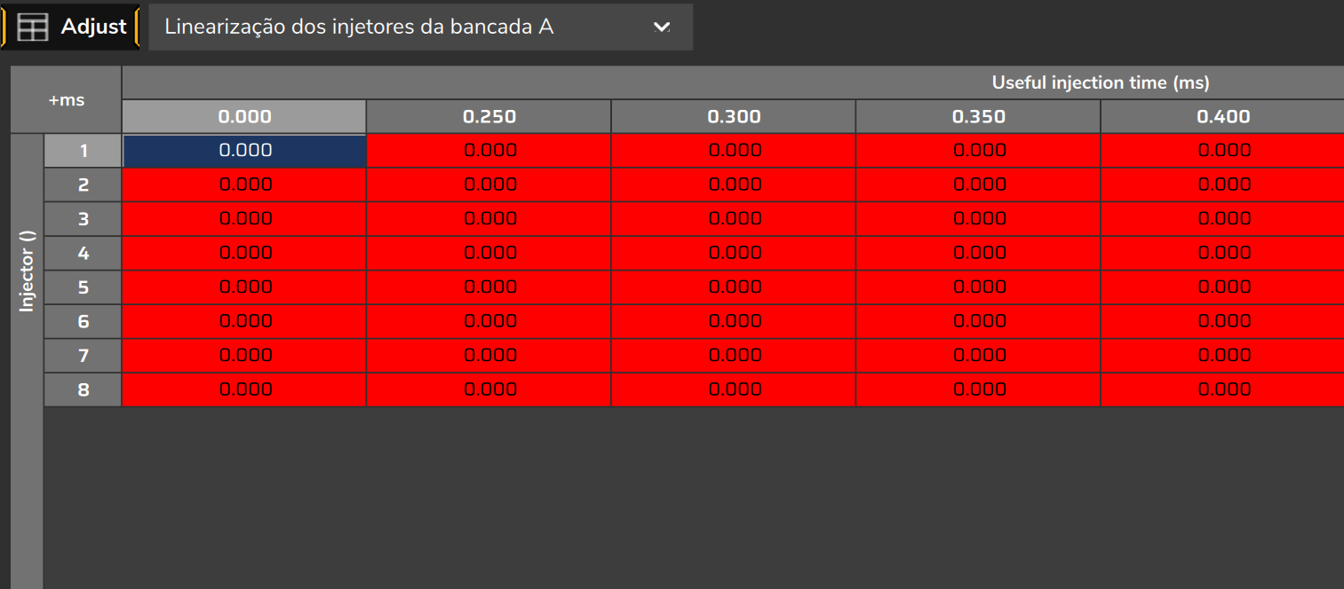
The rows (Injector) are cylinders 1 to 16; the columns are the Useful injection time, from 0 to 3.00 ms on the new map.
It starts zeroed, even when the base map wizard uses an injector from the database: the tuning is up to you.
The Injection time A channel is the useful time plus the deadtime, without the linearization. The applied linearization shows in Injection time Cylinder 01 - A and following ones.
The linearization table has no live cursor. To find the column the engine is in, use the log: Injection time A minus Primary injectors deadtime, with the individual cylinder trim zeroed.
Three cautions on the table:
- the last column stays at 0, because its value applies to every longer pulse;
- from one column to the next the value must not fall by more than the distance between them, otherwise asking for more fuel delivers less;
- without per-cylinder measurement, leave all the rows equal.
Zero useful time gets no linearization: it does not open an injector that the calculation told to stay closed.
To edit, type the value (3 decimal places) or use Shift and the "+" key, which adds 0.001 ms. The "+" key alone adds 0.5 ms, too much for this table.
Tune flow and deadtime first and the linearization last. How to separate VE error, deadtime error and linearization error, and the deadtime yardstick relative to the pulse, are in Step-by-step tuning method.
#Sensors used by VE
The VE sensor configuration is in Engine Settings > Fuel injection, Sensors and failsafe tab (Sensor configuration - VE block). The tab only appears with VE Based.
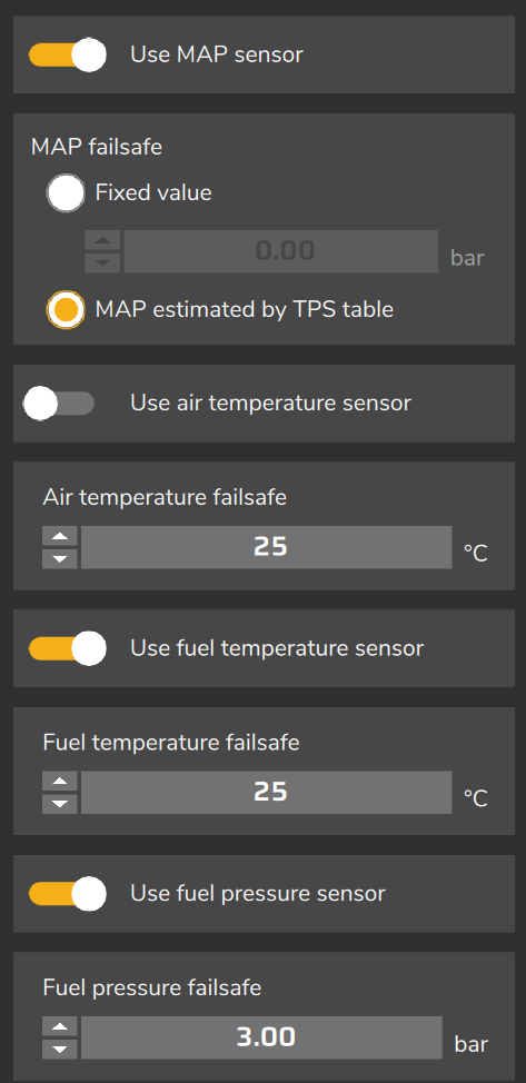
Each sensor has a Use ... sensor switch and a failsafe value, used when the switch is off or the sensor is in failure.
| Option | Default | Factory failsafe | With no sensor on the vehicle |
|---|---|---|---|
| Use MAP sensor | on | MAP estimated by TPS table | Leave it on: if off, learning does not run |
| Use air temperature sensor | on | 25 °C | Turn it off |
| Use fuel temperature sensor | on | 25 °C | No effect on the VE calculation |
| Use fuel pressure sensor | on | 3.00 bar | Turn it off and set the failsafe |
#Manifold pressure (MAP)
The MAP source is chosen in Sensors and calibration > MAP sensor > Sensor mode: internal or external sensor as primary, with or without backup. By default, the internal sensor, with no backup.
The MAP on the screen is gauge pressure, and the VCU has no barometric sensor: see How the VCU calculates fuel in VE mode and What makes VE advanced, and the limits. Do not use the Calibration field of the MAP sensor to zero the sensor on site.
The 4000 rpm MAP failure limiter only arms with an external MAP sensor as primary: with it in failure, no valid backup sensor taking over the reading, and Use MAP sensor on, the VCU switches to the failsafe and limits the RPM to 4000 rpm, cutting the ignition; the cut shows in the cut list. To count on this limiter, choose an external sensor as primary in Sensor mode.
The table accepts values from −1 to +6 bar, and the other option, Fixed value, uses Manifold pressure failsafe (−0.30 bar by default). The VCU uses whatever is there, with no clamp. The table is in The tables: VE, lambda target, axes and grids.
Turning Use MAP sensor off makes the calculation always use the failsafe, without the 4000 rpm cut, and learning does not run.
#Fuel pressure
The differential pressure, line minus manifold, enters the injection time through the square root and selects the deadtime row.
A new map expects a fuel pressure sensor on analog input #6, with the 150 psi sensor already chosen, and comes with Use fuel pressure sensor on.
With the sensor, the calculation uses line minus MAP, both in gauge pressure. Check in the log that Fuel pressure rises and falls with the MAP (on a 3 bar manifold-referenced regulator, near 2.4 bar at idle and 4.0 bar at +1 bar) and that Differential fuel pressure stays near 3 bar.
Without a sensor, turn Use fuel pressure sensor off and set Fuel pressure failsafe to the regulator pressure above the manifold: 3.00 bar on a 3 bar manifold-referenced regulator. When off, the VCU uses the failsafe as a fixed differential pressure.
That value must be the working pressure: a 3 bar failsafe on a 4 bar car leaves the engine about 15% rich, and learning hides that inside the VE.
With the switch off, the VCU assumes constant differential pressure, which is only valid for a manifold-referenced regulator. A fixed-pressure line needs the sensor: with 3.0 bar fixed and +1 bar in the manifold, the 0.85 lambda requested comes out near 1.04.
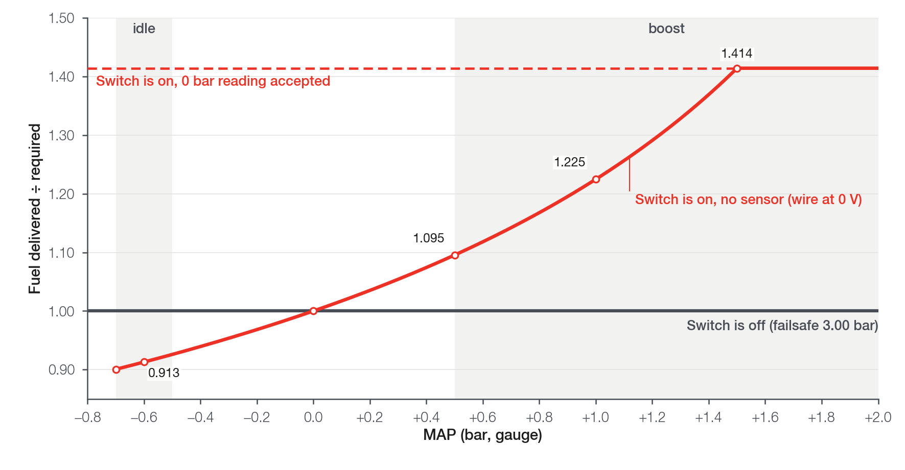
On and with no sensor, when the VCU reports the input as shorted or disconnected (voltage below 0.05 V or above 4.95 V), it assumes 3 bar of line pressure and subtracts the MAP. On a manifold-referenced regulator that gives 22.5% more fuel at +1 bar, 41.4% more from +1.5 bar up, 8.7% less at idle at −0.6 bar, and learning is blocked.
Depending on the voltage of the loose wire, the VCU may not detect the failure and accept 0 bar as a valid reading: it then puts 41% more fuel across the whole map.
How to recognize it: Fuel pressure stuck at 0.00 bar with the engine running (or at the end of the sensor scale, 10.34 bar on the 150 psi one, if the loose wire sits at high voltage), and Differential fuel pressure falling along with the boost (near 3.6 bar at idle and 2.0 bar at +1 bar) or below 1 bar, reaching zero or a negative value on boost. The fuel pressure alarms and the closed loop are off by default: check these two channels in the log.
#Air temperature
The VCU uses the sensor only with the switch on, a valid reading and between −30 and 120 °C; outside that it uses the Air temperature failsafe (25 °C by default).
A sensor stuck at 0 °C passes that range and, with the air at 25 °C, enriches the whole map by about 9%. Fix the sensor before turning the switch on.
With no sensor, turn Use air temperature sensor off: on and with no reading, learning does not run. Off, the calculation uses 25 °C: with the manifold at 50 °C, about 8% more fuel than needed.
In VE there is no Intake air temperature compensation of the pulsewidth mode: the temperature acts through the physics of the calculation.
#Fuel temperature
In VE mode, Use fuel temperature sensor and the Fuel temperature failsafe do not enter the calculation: changing the switch or the failsafe does not change the injection time. Leave them as they are.
#O2 sensors for the closed loop
The VE closed loop reads Closed Loop / VE Probe: the average of the sensors checked in Sensors and calibration > Wide band O2 sensor > Sensor selection for average value. By default, only O2 General is checked. Which readings enter the average and what it changes in the correction is in VE closed loop.
The FT700 has two internal O2 sensor conditioners (the wideband controller circuit that reads the sensor) and the FT470 has one. Each conditioner serves one sensor; the others come in through an analog input or CAN.
#Editing live or writing the map
Flow rate of each primary injector, Primary injector rated pressure, Engine volume, Number of cylinders and Fuel do not change the injection time while you type. They enter a calculation that FuelTech Vision does when the map is saved.
The rated pressure typed changes right away only the minimum pressure limit and the learning window: learning may be blocked before the injection time changes.
On the FT700 screen, save the screen or answer Yes at There are unsaved changes!. FuelTech Vision sends the VCU only what changed, and the injection time changes right after, even with the engine running.
If you answer No, the original value goes back to the VCU immediately.
After saving these screens, Pending changes! appears. The VE calculation is already in effect; the message concerns settings that complete at restart. When you turn the engine off, the VCU restarts by itself in about 1 s.
On the computer, saving sends nothing to the VCU: use the Write button (tooltip Write VCU). When this guide says to write or send the map to the VCU, it means this button.
Example of the jump: changing the flow from 80 to 60 lb/h increases the injection time by 33% at the moment the map reaches the VCU.
These are live: deadtime, linearization, Primary injector opening to bring in the next bank, the failsafe values and the MAP failsafe mode. These are not live: the Use ... sensor switches and the Fuel strategy.
#FT470: what changes
The FT470 runs the same VE mode as the FT700: the same VE table, lambda target, closed loop with learning and acceleration fuel enrichment. The VE screens are the same; only the one for the second O2 sensor conditioner is missing.
The table compares the hardware of the two VCUs in what changes for VE: how many sensors and injectors you connect, how many O2 sensors have an internal conditioner and the log speed.
| Item | FT700 | FT470 |
|---|---|---|
| Dedicated analog inputs | 36 | 7 |
| Flex IO pins (input or output, never both) | none | 20: 8 blue, 8 gray and 4 yellow |
| Injection outputs | 16 | 8: the blue Flex IOs, in output mode |
| Internal O2 sensor conditioners | 2 | 1 |
| Maximum log rate | 1 kHz | 100 Hz |
| Live data to the computer | 1 kHz | 100 Hz |
| Overwrite a section current map (overwrites part of the current map) | yes | no |
On the FT470, a Flex IO used as an output is no longer an input (the gray ones are the ignition outputs). Before changing a blue Flex IO to input, check it has no injector: one on an input-mode pin can leave the engine with no injection.
On the new map, the TPS is assigned to input #11, which on the FT470 is a blue Flex IO in output mode. Move the TPS to a dedicated input or change that pin to input; FuelTech Vision warns while the TPS has no input.
A typical VE map uses four dedicated inputs: engine temperature, air temperature, fuel pressure and TPS. Three dedicated ones are left, plus the Flex IOs not used as outputs. An air temperature or fuel pressure sensor that is not installed: turn off its Use ... sensor switch (see Sensors used by VE, in this chapter).
For VE tuning this guide recommends 100 Hz, the FT470 limit. The wizard's new map logs at 50 Hz with no VE channel: before running, set the Sampling rate to 100 Hz and enable the channels in Reading the log: the VE channels.
The FT470 has no Overwrite a section current map: after correcting the VE, write the whole map.
Changing ECU model in Map options from FT700 to FT470 does not remap inputs and outputs: FuelTech Vision only hides what the FT470 lacks and limits the log rate. Review sensors, TPS, O2 sensors and injection outputs by hand.
With 8 injection outputs, an engine of up to 8 cylinders with one sequential bank fits. After changing the number of cylinders or the injection mode, check in the output list which pin each injector ended up on.