13. Diagnosis: symptoms and causes
The tables in this chapter go from the symptom to what to look at, to the most probable cause and to the action.
Use a log in steady state, with the engine warm and the closed loop channels visible (see Reading the log: the VE channels). MAP pressures are in gauge bar, as on the screen.
#Where to start
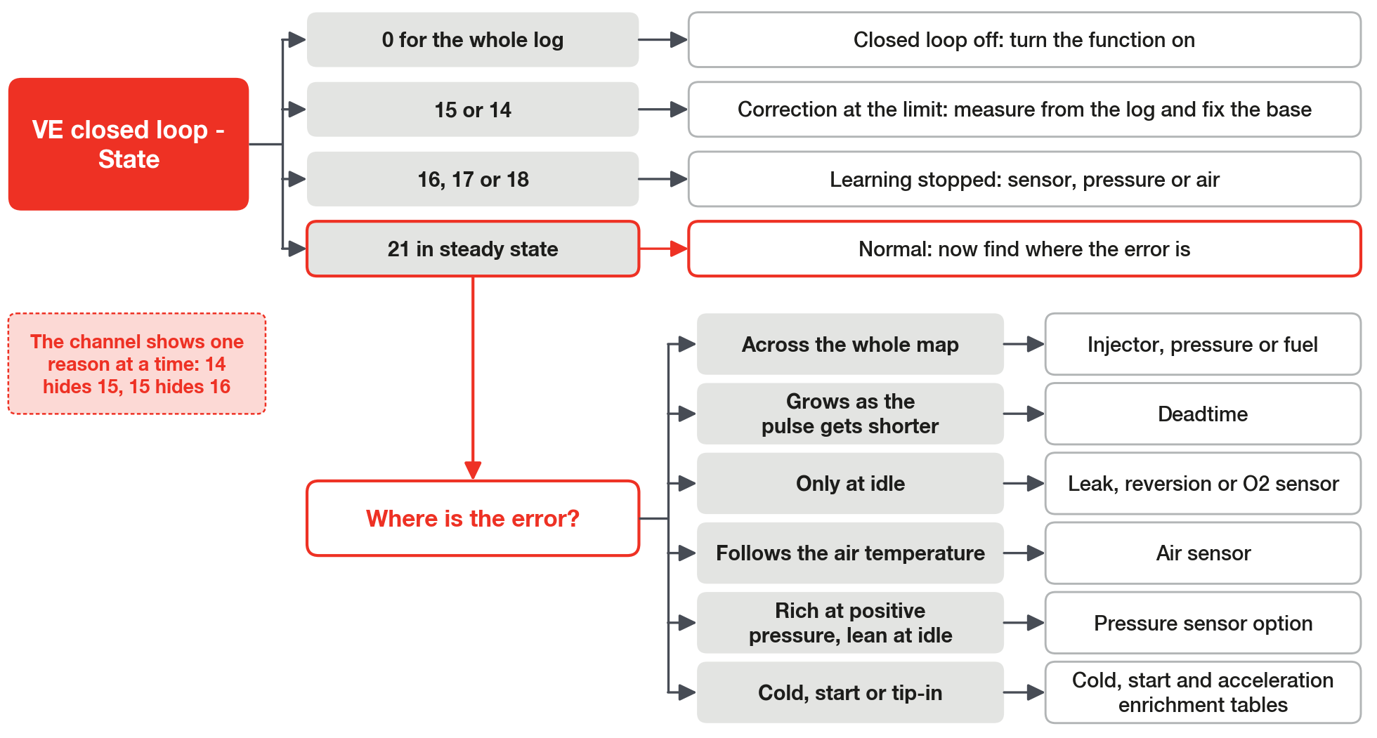
Start with the channel VE closed loop - State: it says why the closed loop is not correcting or not learning.
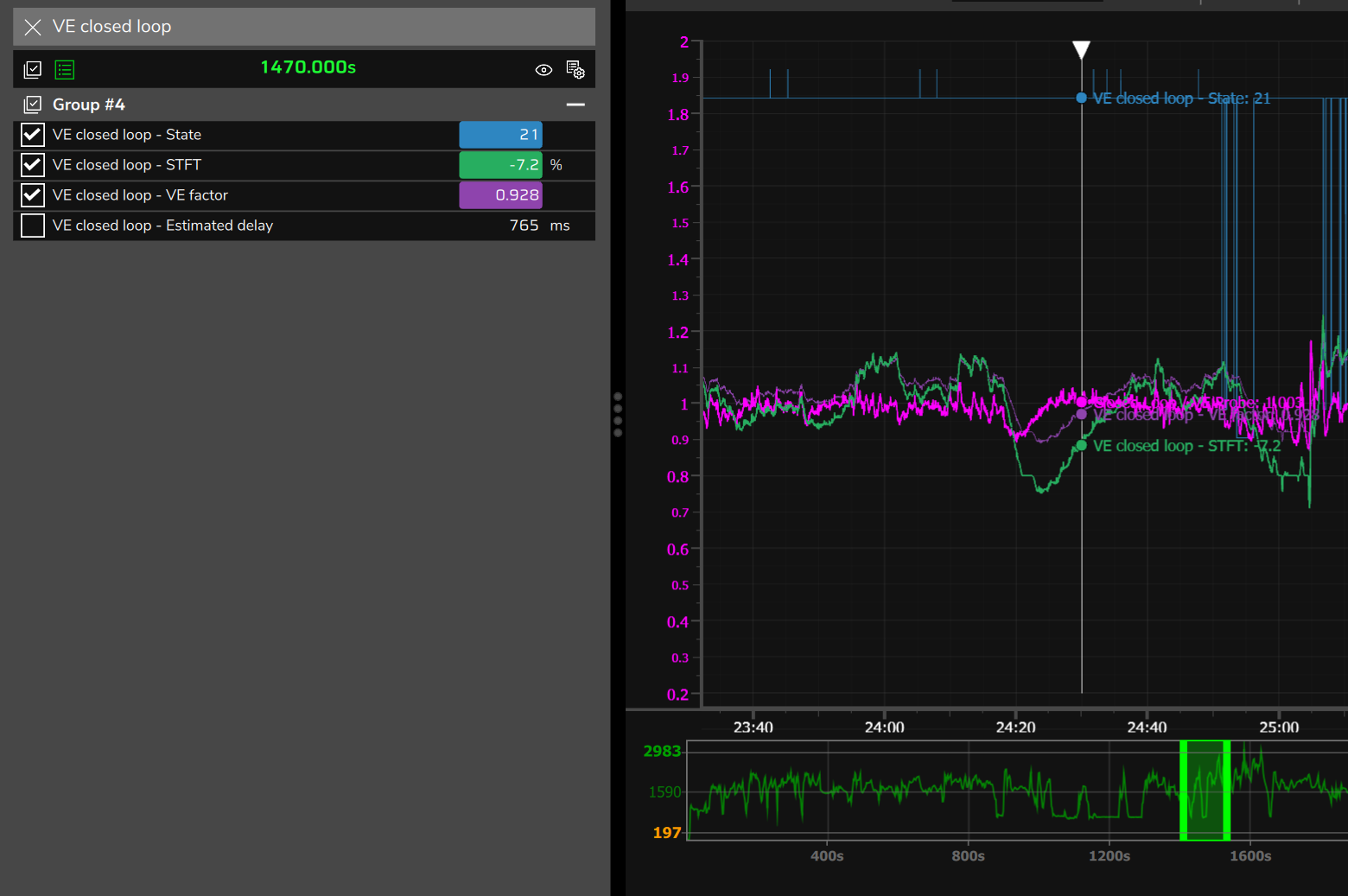
In the log the state shows up as a number; the VE learning (LTFT) screen, on the Live page, shows the reason in text. The complete list is in Reading the log: the VE channels.
The channel shows one reason at a time, the one of highest priority. Before concluding that a reason did not happen, check that another one did not hide it: state 14 hides 15, and 15 hides 16.
After the state, see where the error shows up: across the whole map, in one type of pulse, in one region or in one condition (cold, start, tip-in).
#Closed loop stopped or at the limit
| Symptom | What to look at | Probable cause | Action |
|---|---|---|---|
| The closed loop never corrects | VE closed loop - State at 0 for the whole log; VE closed loop - STFT at zero; VE closed loop - VE factor at 1.000 | Fuel closed loop (VE) off, the default | Turn the function on. |
| Correction pinned at the limit; state 15, STFT saturated (VE probably wrong) | VE closed loop - STFT stuck at the limit (±10% at vacuum; +5/−3% from 1 bar upward); the MAP tells which column of Fast correction (STFT) limits by MAP applies | The VE of the region is off by more than the limit. Same sign across the whole map: injector, pressure or fuel | Do not raise the limit or the gain. Measure the required VE from the log, correct the VE or the source and clear the learning. |
| State 14, Total authority reached | VE closed loop - VE factor at 0.75 or 1.25 (with the default) | Correction and learning added up to the ceiling of Total authority (STFT + LTFT), 25% by default | The base is wrong: same action as state 15. |
| VE closed loop - Estimated delay stuck at 2500 ms with the engine running | State other than 0; VE total flow above zero | Exhaust transport constant inherited at 1.5. With state 0 for the whole log, it is only the closed loop being off | Set 0.02 s·l/min (default): by the VCU calculation, the estimated delay is about 0.6 to 1.3 s at idle, depending on consumption, and near 0.2 s at cruise. |
While the correction is at the limit, the learning also stays at the limit. With Apply the learned LTFT off, a 20% error in a region shows up as about 10% at vacuum in the Diagnostic, and Commit to VE proposes half of that (Percentage to apply at 50%).
#Learning that does not happen
| Symptom | What to look at | Probable cause | Action |
|---|---|---|---|
| VE closed loop - Active LTFT always at zero, or missing from the channel list | The Apply the learned LTFT switch; the states in the log | Off (default): channel always zero. On: VE already right, learning off, only positive pressure or constant lockout | See the learned table in VE learning (LTFT) > Live, with the VCU connected. |
| State 16, VE model sensor in failsafe | MAP, Air temperature - intake and Fuel pressure: zeroed, frozen or out of range | Sensor option on with no sensor or with an invalid reading; Use MAP sensor off; air outside −30 to 120 °C | No air or pressure sensor: turn the option off and set the real value in the failsafe. Use MAP sensor stays on, except on individual throttle bodies of a naturally aspirated engine with no tap representing the runners (see What makes VE advanced, and the limits). With a sensor: fix the reading first. |
| State 17, Fuel pressure out of range | Differential fuel pressure (the screen shows Base fuel pressure) against Primary injector rated pressure | Working pressure more than 10% (default tolerance) away from the entered rated pressure of the injector | Enter the injector at the working pressure, with the flow rate rescaled. |
| State 18, Air temperature out of range | Air temperature - intake | Air outside 15 to 45 °C with the defaults; the lockout applies even with the sensor turned off in the model | The correction continues. To learn, run with the air in range and check Air temperature range for learning. |
| State 10, Target moving, repeating at idle | The lambda target where idle wanders | Target on a ramp in the idle region | Leave the target flat in the idle region. |
| State 21, Correcting (waiting for cell to stabilize), in steady state, with no learning | VE closed loop - STFT below 1.5% | Normal state: the cell is already right and there is nothing to learn | None. The cell does not need Commit to VE. |
The sensor options (Use MAP sensor, Use air temperature sensor and Use fuel pressure sensor, on by default) and how to enter the injector at the working pressure are in Before you start: engine, fuel, injectors and sensors. Do not use Differential pressure tolerance for learning for this.
In the case with no pressure sensor and the switch on, the closed loop does not cover the error at positive pressure (the numbers are in Before you start: engine, fuel, injectors and sensors): the default limit there is +5/−3%.
With the air temperature off and the default failsafe (25 °C): with the air at 60 °C the engine receives about 12% more fuel; with the air at 0 °C, about 8% less.
#Mixture off in a region
| Symptom | What to look at | Probable cause | Action |
|---|---|---|---|
| Equal error across the whole map | Global error (flow / pressure / stoich) in the Diagnostic; in the log, VE closed loop - STFT with the same sign in all regions | Injector flow rate or rated pressure; pressure failsafe; fuel or ethanol; air temperature off | Correct the source, not the VE (section Global error: correct the source, further on). |
| Error that grows as the pulse gets shorter | Deadtime (correlation with 1/PW) in the Diagnostic; in the log, the error against the useful time and the deadtime fraction | Wrong deadtime table; pulse below the linear range of the injector; wrong pressure failsafe | Correct the deadtime before the VE; linearization for very short pulses; do not correct VE on a short pulse. |
| Rich or lean only at idle | Idle only (additive: leak / reversion / O2 sensor) in the Diagnostic; the sensors of each cylinder bank; state 5 or 10 at idle | Air leak, exhaust reversion or sensor position; Minimum RPM above idle; target on a ramp | Look for the physical cause; keep Minimum RPM below idle; do not carry the idle error into the VE. |
| Error that follows the air temperature | Charge temperature (correlation with IAT) in the Diagnostic; Air temperature - intake; Use air temperature sensor | Sensor off (the failsafe applies, 25 °C by default) or reading a plausible but wrong value | Fix the reading and only then enable it; never enable it with an impossible value. |
| Rich at positive pressure and lean at idle, with no fuel pressure sensor | Fuel pressure with no reading; Differential fuel pressure falling when the MAP rises; see whether the state goes to 16 | Use fuel pressure sensor on (default) with no sensor: the calculation treats the failsafe as line pressure and subtracts the MAP | Turn the option off and enter the regulator pressure above the manifold as the failsafe, or install the sensor. |
| Lean at positive pressure and rich at idle, fuel line with no reference to the manifold | Differential fuel pressure constant for the whole log; VE closed loop - STFT at +5% at positive pressure | Option off: the calculation assumes a constant pressure difference, but the real one falls when the MAP rises | Install the sensor and turn the option on, or use a manifold-referenced regulator. |
| Lean at the start of a tip-in, after a rich cruise | Negative VE closed loop - STFT frozen in the transient (state 9) | Rich light load: the closed loop carries the negative correction into the tip-in | Correct the light load; use Only enrich above the set pressure or a small negative limit in the load columns. |
#Cold, start and transients
| Symptom | What to look at | Probable cause | Action |
|---|---|---|---|
| Rich with the engine cold | Engine temperature below 70 °C; state 3, 4 or 0; VE - Total enrichment above zero | Error that follows the temperature: temperature compensation too high. A step when the post-start ends: post-start too high | First tune the warm VE; cut the culprit temperature cell little by little; judge with 3 cold starts or more. |
| Hard start | Injection time A, B and C during cranking; Engine temperature; pedal | Wrong start table; pedal at 70% or more (default), which zeroes the pulse of the Engine start fuel injection table; a bank that cranks the engine with no injection at start | Check the start mode and switch of each bank; tune Engine start; start without pressing the pedal. |
| Rich start and warm-up with no effect | Engine temperature with no valid reading | Sensor failure: the start uses the 0 °C row, and warm-up and post-start do not act | Fix the sensor before touching the tables. |
| Sensor at 0.000 on a cold start | Closed Loop / VE Probe at 0.000; Lambda error (O2 sensor vs target) at zero; state 1 or 2 | Sensor warming up or with no valid reading, normal in the first seconds. If it persists: failure, or sensor outside the selection | Do not read it as lean: discard the segment. Start the log before turning the key on. |
| Acceleration fuel enrichment firing with a steady foot | TPS moving without the pedal; Acceleration fuel enrichment above zero; state 8 repeating at idle | Throttle commanded by another module; pedal compensation active; low trigger | Another module: raise Minimum variation of TPS/MAP for pump shot (there the Pedal source copies the TPS). Pedal compensation: Pedal source. Small shot: adjust Minimum acceleration fuel enrichment that freezes the correction. |
When cold, check how much of the enrichment reached the combustion: (sensor ÷ target) × (1 + enrichment ÷ 100).
The reading is an indication, not a measurement. Near 1.00, the extra showed up whole in the sensor: a sign that it is in excess in the table. Above 1.00, part of it probably stayed on the wall, and the cold engine needed it. Below 1.00, suspect a rich base: VE or injector.
With the electronic throttle commanded by the VCU itself, the TPS channel is the commanded demand, counted from the idle position: it stays at zero at idle, even with the throttle moving. If it moves at idle without the pedal, check whether the throttle is commanded by another module or whether a pedal compensation is active.
#Deadtime or leak
Both signatures show up at idle, where the pulse is short, and so they get confused.
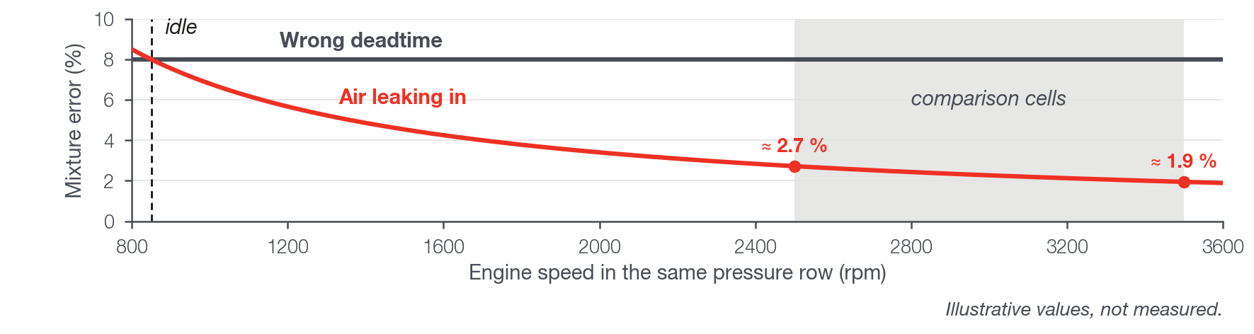
A wrong deadtime generates an error that depends on the pulse size: the deadtime deviation divided by the useful time.
Air leaking in should generate, by the same reasoning, an error that depends on how much air the engine draws per second: the leak flow divided by the flow drawn in.
To separate them, compare idle with cells of the same pressure row at a higher engine speed, for example 2500 to 3500 rpm at the same vacuum.
There the pulse per cycle is almost the same as at idle, but the engine draws about 3 to 4 times more air per second (with idle near 850 rpm).
The test comes from these two calculations and serves as guidance: if the error stays the same, it points to deadtime; if it falls in proportion to the engine speed, to air leaking in, the exhaust or the sensor.
The Diagnostic page separates the two signatures. The idle error, however, is not discounted from what Apply to VE carries to the table: correct the cause before applying.
#Global error: correct the source
The Diagnostic flags a global error when the average exceeds 3%, up or down, with a spread below 2%. It only analyzes with at least 4 cells that reach the Minimum confidence (hits).
In VE mode the entered flow rate goes straight into the calculation: an injector entered as 40% larger than the real one receives almost 30% less fuel, and the lambda ends up about 40% above the target.
A global error of +X% means fuel was missing. If the source is the flow rate, the entered one is too high: divide the flow rate by (1 + X ÷ 100).
Example: global error of +5% with an injector entered at 80 lb/h. Corrected flow rate: 80 ÷ 1.05 = 76.2 lb/h.
If the correction was at the limit during the collection, the X is clipped at the limit. Measure the real error from the log.