7. From the pulsewidth map to VE
This chapter takes a map that works by injection time to VE mode without losing the tune it already has. FuelTech Vision does not convert the map by itself: the conversion is a per-cell calculation, which you do with your engine's numbers and can check backwards.
If the engine has no map yet, start with the base map wizard, described below, and skip the inverse calculation.
#What happens when you change the strategy
Changing the Fuel strategy to VE Based does not calculate or copy any table. It changes what appears on the screen and which tables the VCU uses.
The Main MAP VE table and the Lambda target table by MAP keep what was already saved in the file.
On a map that never ran in VE, that is the factory default: a generic VE, from 20.8% to 104.1%, and a generic lambda target, equal at all RPMs. Neither has any relation to your engine: without the conversion, the engine runs on a VE that is not its own.
The pulsewidth tables remain in the file, only hidden. The closed loop and the acceleration fuel enrichment of the pulsewidth mode are turned off when the map is sent to the VCU, but keep their values for when you go back to Injector Pulsewidth.
Even so, save a copy of the pulsewidth map under another name before switching: it is where you will read the numbers for the calculation.
#What stays the same and what stops acting
These stay the same in both modes, with the same table: warm-up, post-start, gear compensation, bank compensation, individual cylinder trims and the injector deadtime table. With the VE closed loop on, however, the warm-up above the loop's minimum temperature and the gear compensation start to be subtracted as error: see Enrichments and compensations in VE mode.
Several pulsewidth mode functions do not act in VE, among them the Overall fuel trim, the Intake air temperature compensation and the TPS, MAP and RPM compensations; with Flex fuel, the ethanol-based ignition compensation does not act either. The full list is in Enrichments and compensations in VE mode.
If the old map relied on one of them to tune the mixture at steady state, that effect has to go into the converted VE or into the lambda target.
Two VE functions are off by default: the VE mode Acceleration fuel enrichment and decay and the Fuel closed loop (VE).
The VE acceleration fuel enrichment is a different function, in percent of the fuel, and does not inherit the acceleration tune of the pulsewidth mode.
Changing the strategy does not touch the outputs. FuelTech Vision only reassigns outputs by itself when the engine type or the number of cylinders (or rotors) changes.
#The base map wizard
The Step-by-step map wizard, with the Volumetric Efficiency (VE) strategy, generates a VE from scratch. It does not read the pulsewidth map you already have.
The VE comes from the displacement, the number of cylinders, the maximum torque RPM, the cut RPM, the Aspiration, the Engine profile and, with Turbo or Supercharger, the Max. boost pressure (bar). The chosen fuel does not enter the generated VE.
The result always stays between 30% and 115%. The generated peak is about 85 to 90% on a Naturally aspirated engine with Engine profile at Stock / Street, and reaches about 102 to 108% with Supercharger and Engine profile at Competition.
The wizard leaves the Primary injector linearization zeroed, even with the injector chosen from the list. With a large injector, fill it in before tuning the idle, as in Before you start: engine, fuel, injectors and sensors.
The wizard's Time based (ms) option does the reverse path, from VE to time, and also does not read the existing table.
Use the wizard for an engine with no map. On an engine that already runs well on pulsewidth, the conversion preserves a tune that the wizard does not know.
#Map imported from the PowerFT line
The imported map arrives as a new map, in Injector Pulsewidth. There is no direct import to VE.
The flow of each injector comes from the old map's total flow divided by the number of cylinders.
After importing, check the Primary injector rated pressure: the import does not bring that value, and the field stays at the default of 3 bar.
The path is to import, check the pulsewidth map on the engine and only then convert using this chapter's calculation.
#The inverse calculation
In VE mode, the VCU calculates the air mass of each cycle and, from it, the fuel (see How the VCU calculates fuel in VE mode). Converting is doing that calculation backwards: for each cell, find the VE that gives the same fuel the pulsewidth map's pulse gave.
Two details of the pulsewidth mode decide whether the calculation is right.
The pulsewidth table value is the total pulse, with the reference deadtime already included. The part that injects fuel is the table value minus the Reference deadtime for primaries injectors.
That field only appears in pulsewidth mode, on the Injector configuration screen. Note the value of each bank before changing the strategy.
With the Primary mode at Multipoint and a piston engine, the injector opens twice per cycle, each time with the full table value. In the calculation, use double the useful time.
In Semi-sequential and Sequential, the injector opens once per cycle and there is no doubling.
useful time (ms) = table value − reference deadtime   (× 2 in Multipoint)
fuel (mg)        = useful time × injector flow (mg/ms)
air at 100% (mg) = 1000 × (MAP + 1.01325) × V ÷ (0.0028705 × (T + 273.15))
VE (%) = 100 × fuel × AFR × lambda ÷ air at 100%- MAP: the pressure of the cell's row, in bar gauge, as the screen shows. The VCU adds a fixed 1.01325 bar, with no barometer, and uses the result as absolute pressure; the calculation does the same.
- V: displacement divided by the number of cylinders, in liters. The number 0.0028705 is the air constant in bar, liter, gram and kelvin.
- T: air temperature at which the map was tuned, in °C. With no air temperature sensor, use the Air temperature failsafe, which is the value the VCU will use.
- AFR: the stoichiometric AFR the VCU will use in VE: that of the fuel configured in the map or, with Flex fuel active, that of the blend at the ethanol content of the tune (formula in Before you start: engine, fuel, injectors and sensors). Lambda: what the engine was getting in that cell.
- Flow in mg/ms = flow in lb/h × 0.126, at the injector's rated pressure.
- If the differential pressure the VCU will use in the cell is different from the rated pressure, multiply the flow by √(differential pressure ÷ rated pressure). The VCU never uses less than half of the rated one.
If the calculation and the map use the same injector, displacement and fuel numbers, and the lambda target receives the same lambda as the calculation, the engine gets in VE the same pulse it got by time, at the air temperature and fuel pressure of the tune.
Outside those conditions, VE mode corrects through the physics of the calculation. On a day 20 °C colder than the tune, VE gives about 7% more fuel; the pulsewidth map, with the default compensation, gave about 1%.
An injector entered slightly different from the real one does not change the pulse, if the same number goes into the calculation and into the map. It only removes the physical meaning of the VE and gets in the way when you change injectors later.
An AFR in the calculation different from the one configured in the map, however, changes the pulse in every cell: 9.0 in the calculation and 8.4 in the map give 7.1% more fuel.
#From the table or from the log
The calculation can start from the pulsewidth map's table or from a log made with it. The log is better: the table repeats the old map, with its errors. The log shows the pulse that actually came out, and the O2 sensor shows the mixture that actually resulted.
From the log, the useful time is Injection time A minus Primary injectors deadtime, and the lambda is that of Closed Loop / VE Probe, the average of the sensors the VE loop will read. Use the MAP and the Air temperature - intake from the same instant.
Choose steady-state segments, with steady pedal and MAP and with the engine warm: in pulsewidth mode, Injection time A already includes all the corrections and the acceleration fuel enrichment. In Multipoint, use double here too.
#Step-by-step recipe
- Save a copy of the pulsewidth map. Still in pulsewidth mode, note for each bank the reference deadtime, the flow, the rated pressure and the bank mode.
- Also note what was active in the tune: Overall fuel trim, Intake air temperature compensation, Differential fuel pressure deviation compensation with its reference, and the tune's air temperature. With Flex fuel, note the ethanol content of the tune and the Main fuel injection compensation tables (MAP and TPS versions) and O2 closed loop target compensation (TPS version): in VE they do not act, and their effect has to go into the VE or the target.
- Change the Fuel strategy to VE Based and configure the fuel, injectors and VE sensors. The numbers that go in the map are the same as in the calculation.
- Define the VE and target grid, as in Grid and resampling, just below.
- For each cell, calculate the useful time. Multiply by the overall trim (1 + percentage ÷ 100), by the air temperature compensation at the tune's temperature, also as (1 + percentage ÷ 100), if it was on, and by 2 in Multipoint.
- If the pulsewidth map was by pressure only, with RPM compensation, do the calculation RPM by RPM, with each RPM's compensation.
- Calculate the VE with the lambda the map really delivered and write the same lambda in the Lambda target table by MAP.
- Fill the cells outside the old map, check the table shape, send the map and follow Before the first start.
On the default Intake air temperature compensation table, the value at 40 °C is +2.0%.
#Checked example
2.0 L 4-cylinder engine, turbo, hydrous ethanol (AFR 8.4), 80 lb/h injectors at 3 bar and a manifold-referenced regulator with 3 bar of differential pressure.
Sequential injection, reference deadtime of 1.00 ms, map tuned with the air at 40 °C, no overall trim and no air temperature compensation.
Cell at 4000 rpm and +1.00 bar, with 15.00 ms in the table and lambda 0.80:
useful time = 15.00 − 1.00 = 14.00 ms
flow        = 80 × 0.126 = 10.08 mg/ms
fuel        = 14.00 × 10.08 = 141.1 mg
air at 100% = 1000 × 2.01325 × 0.5 ÷ (0.0028705 × 313.15) = 1119.8 mg
VE          = 100 × 141.1 × 8.4 × 0.80 ÷ 1119.8 = 84.7%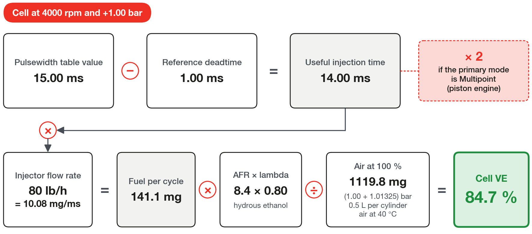
The same calculation on the other cells of the same engine:
| Cell | Table (useful time) | Lambda | VE |
|---|---|---|---|
| 900 rpm, −0.65 bar | 2.10 ms (1.10 ms) | 1.00 | 46.1% |
| 2500 rpm, −0.40 bar | 3.40 ms (2.40 ms) | 1.00 | 59.6% |
| 4000 rpm, +1.00 bar | 15.00 ms (14.00 ms) | 0.80 | 84.7% |
With these VEs, the VCU's equation returns 1.10, 2.40 and 14.00 ms of useful time, with a difference below 0.01 ms. The conversion did not change the fuel.
Entering 72 lb/h instead of 80, in the calculation and in the map, lowers the last cell's VE to 76.2% and keeps the 14.00 ms.
#The reference deadtime matters more at idle
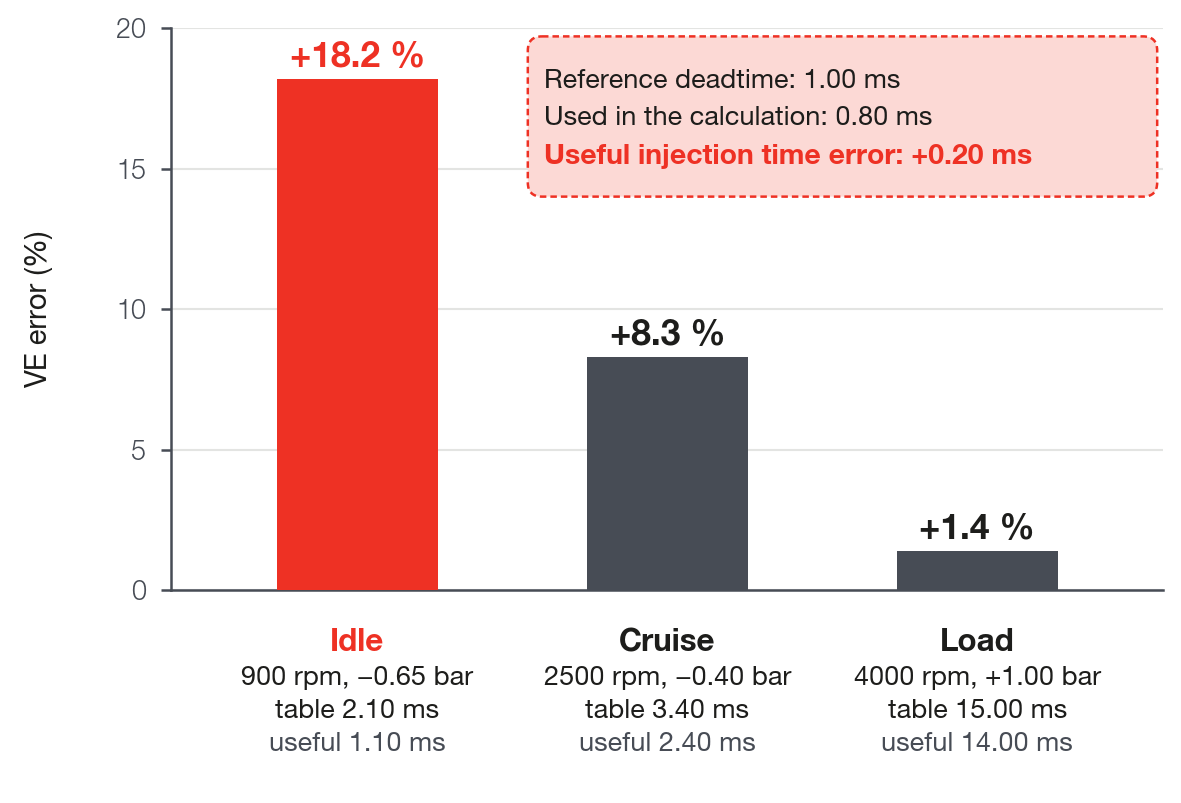
Getting the reference deadtime wrong by 0.20 ms, using 0.80 instead of 1.00, changes the example's VE by +18.2% at idle, +8.3% at cruise and +1.4% at load.
The error is fixed in milliseconds. On a short pulse it is large in proportion; on a long pulse, it nearly disappears.
Forgetting the Multipoint doubling leaves the VE at half.
#Cautions
#Grid and resampling
The VE grid does not have to be that of the pulsewidth map: the recommended one, 16 × 16 for the VE and 10 × 10 for the target, with equally spaced axes, is in The tables: VE, lambda target, axes and grids. If you resample, check the table shape again on the final grid.
#Cells the engine never visited
The VCU does not extrapolate: outside the axis, the edge cell applies. In VE, even with the VE held at the edge, the fuel keeps rising with manifold pressure.
Do not calculate the VE for a cell that lies outside the old map's axes. The pulsewidth table returns the edge pulse over more air, and the calculation invents a VE that falls with pressure: lean mixture.
Leave those cells equal to the neighbor or richer, never leaner, and treat them as provisional until the log passes through them.
#Pressure: gauge on the axis, absolute in the calculation
The pressure axis of the VE and of the target is gauge pressure in bar, as the MAP appears on the screen; a map with an absolute kPa axis is converted as in The tables: VE, lambda target, axes and grids.
A pulsewidth map built by TPS, common on individual throttle bodies, does not convert cell by cell: the VE is always by RPM and MAP. Use the log to find out at what MAP the engine runs at each opening.
#Fuel pressure and regulator
The calculation needs the same differential pressure the VCU will use in VE. Set up the pressure sensor before converting, in Engine Settings > Fuel injection, Sensors and failsafe tab, which only appears with VE Based.
With no sensor and a manifold-referenced regulator, turn Use fuel pressure sensor off, which is on by default, and enter the regulator pressure in Fuel pressure failsafe.
A regulator with no manifold reference needs the pressure sensor installed. The why is in Before you start: engine, fuel, injectors and sensors.
On a direct injection engine, follow that chapter's direct injection recipe and keep in VE the same Differential fuel pressure deviation compensation and the same reference as the old map. That way, in the calculation from the table, the rail pressure drops out of the calculation. From the log it does not drop out: Injection time A already comes multiplied by that compensation. Divide the useful time by that chapter's direct injection factor, or do the calculation from the table, which in this case is the simplest.
#Banks
VE has a single table for the whole engine. The VCU splits the fuel among the banks in the order A, B and C, and the primary must be A.
In the calculation, use the sum of the fuel from the banks that were injecting in that cell.
Primary injector opening to bring in the next bank is bank A's opening ceiling before B comes in, with a default of 100%. Set it so that B comes in near where it did on the old map and check in the log.
#Deadtime and linearization
The deadtime table is the same in both modes and remains valid. In VE, the deadtime is added to each pulse, on top of the calculated useful time.
Primary injector linearization is read differently: in pulsewidth mode, by the total pulse time; in VE, by the useful time, which is the Useful injection time axis on the screen.
After the conversion, a linearization tuned in pulsewidth mode ends up shifted on the axis by the deadtime value. The effect shows on short pulses: check the idle and light load in the log.
#Outputs and sanity test
In the conversion, do not change the engine type or the number of cylinders, because that is what triggers the automatic output reassignment. If you did, check the output diagram before starting.
If the converted VE goes above about 115% at the point of best filling, check the entered flow, the fuel pressure and the air temperature sensor before running. It is not a ceiling, it is an alarm: see Step-by-step tuning method.
#Before the first start
A new map and a converted map bring factory values that change the fuel. Check each line before starting; the detail is in the chapter cited or in this one.
| Item | Factory | Check |
|---|---|---|
| Fuel strategy, VE and target | Injector Pulsewidth; generic VE and target, with no warning that they were not converted | VE Based, with the VE and the target converted |
| Engine volume and Number of cylinders | 0 and 8; with volume 0 the bank does not inject by VE | those of the engine |
| Fuel | Pure gasoline (E0); in Custom, the AFR may show 1.00 | the one in the tank, equal to the calculation's; in Custom, the AFR of your fuel |
| Flow rate of each primary injector | 230 lb/h | that of one injector, equal to the calculation's |
| Primary injector rated pressure | 3.00 bar | the working differential pressure, paired with the flow (Before you start: engine, fuel, injectors and sensors) |
| Deadtime and linearization | generic injector, 1.000 ms at 12 V and 3 bar; linearization zeroed | your injector's data, equal to the calculation's |
| Primary mode | Semi-sequential | that of the engine; in Multipoint, the doubling applied in the calculation |
| Use fuel pressure sensor | on | off if the car has no sensor; send the map after changing it |
| MAP failsafe | table that does not go above 0 bar | on a turbo engine, never run without a MAP reading; MAP hose and port checked (Before you start: engine, fuel, injectors and sensors) |
| VE mode Acceleration fuel enrichment and decay | off | on and tuned before driving (Enrichments and compensations in VE mode) |
| Fuel closed loop (VE) | off | on in the first run, with Apply the learned LTFT off |
| Engine temperature compensation and Gear based compensation | +7% at 70 °C and +10% from 120 °C up; the gear one is off by default | zeroed in the range where the loop acts (Enrichments and compensations in VE mode) |
| Only enrich above the set pressure | off | on a turbo engine, decided before the first pull (VE closed loop) |
| Injection mode for engine start bank A | Engine start fuel injection table, which does not compensate weak battery | your choice (see Start in VE mode); on Fuel injection main table, the low RPM columns of the VE no leaner than the ones at higher RPM |
| VE channels in the log | FT470: none enabled on the new map, log at 50 Hz | enabled as in Reading the log: the VE channels; on the FT470, Sampling rate at 100 Hz |
- Effects of the pulsewidth-mode functions that do not act in VE brought into the VE or the target; on a flex car, the ignition table reviewed, because in VE the timing gets no correction for ethanol content; with nitrous, the warning in What does not run in VE mode.
- Outputs checked, if the engine type or the number of cylinders changed.
- Map sent to the VCU and, only then, Clear LTFT on the VE learning (LTFT) screen, with FuelTech Vision connected and the engine off.
#Map from a previous version or new firmware
- Exhaust transport constant: a VE map made in a previous version of FuelTech Vision may bring 1.5; use a value on the order of 0.020 (see VE closed loop).
- Scale of the VE - Efficiency % channel: on a new map it goes from 0 to 179%; on a map from a previous version, check the Maximum (see Reading the log: the VE channels).
- After updating the firmware, check the Memory indicator on the VE learning (LTFT) screen before counting on the old learning.
#The first run
The help of the VE learning (LTFT) screen has a recommended flow. The procedure below follows that flow for a freshly converted map.
Terms in the procedure: the STFT is the fast correction, which follows the O2 sensor; the LTFT is the learning stored per cell in the VCU; the Diagnostic checks whether the learned error really belongs to the VE, and Commit to VE takes the LTFT into the VE table when you command it (see VE closed loop and Self-learning: VE learning (LTFT)).
- Before starting, with the converted map on the VCU, FuelTech Vision connected and the engine off, check that the injector's rated pressure matches the regulator's and press Clear LTFT.
- Start and warm up without counting on the loop. By default, it only corrects with the engine at 70 °C or more and 15 s after the end of post-start.
- With the engine warm and before turning the loop on, check VE - Total enrichment near zero: the Engine temperature compensation from the loop's Minimum engine temperature upward and the Gear based compensation must be zeroed (see Enrichments and compensations in VE mode).
- On a turbo engine, decide on Only enrich above the set pressure before the first pull (see VE closed loop). By default, learning does not write from 1.0 bar up: correct that region from the log.
- Turn on the Fuel closed loop (VE) with the default authority and leave Apply the learned LTFT off.
- In the first minutes at steady state, watch VE closed loop - STFT. If it hits the limit, or if STFT saturated for too long appears, the mixture is farther from the target than the fast correction can reach, and the STFT stuck at the limit does not show the size of the error.
- In that case, correct the VE from the log, save a new version, send it, clear the LTFT and go back to step 6.
- If the difference is the same across the whole range, the error is not in the VE: check injector, pressure and fuel.
- With the loop within the limit, run at steady state in each usage range and follow the collection, the Diagnostic and the first Commit to VE as in Self-learning: VE learning (LTFT).
- Only turn on Apply the learned LTFT when the learned table is small across the whole usage area.
The learning stays in the VCU, not in the map, and does not go away when you write a new map. That is why Clear LTFT comes in step 1, after sending: it also copies the new VE's axes.
With Apply the learned LTFT off, only the fast correction moves the fuel, limited by the Fast correction (STFT) limits by MAP table: by default, up to 10% in vacuum, 8% at the 0 bar column, 5% at the 0.5 bar one and, from 1.0 bar up, 5% up and 3% down. It is the yardstick for the first run.
#What to look at in the log
| Channel | What to check on the first run |
|---|---|
| Closed Loop / VE Probe and VE - O2 closed loop target | The target must be what you wrote in the conversion, not the factory one. |
| Lambda error (O2 sensor vs target) | Positive is leaner than the target. Judge only with the total enrichment near zero. |
| VE - Total enrichment | Near zero with the engine warm at steady state. At +20%, the lambda error shows −16.7% even with the VE right. |
| VE - Efficiency % and VE - Effective efficiency % | The table's VE and the VE with the loop's correction. It can go above 100%: the table accepts up to 300%. |
| VE closed loop - STFT | Far from the limit. At the limit right in the first minutes: error larger than the fast correction can reach (steps 6 and 7 of the first run). |
| Differential fuel pressure (the screen shows Base fuel pressure) | With a manifold-referenced regulator, near the base pressure across the whole range. If it falls along with the boost, check the pressure sensor configuration. |
| Injection time A and Primary injectors deadtime | The part of the pulse that is deadtime shows where the pulse is short and the deadtime matters. |
| Injection duty A | Below 100%. With a bank at 100%, the loop freezes. |
| Air temperature - intake | The converted VE now compensates air temperature through the gas law. |
On a freshly converted map, an error equal across the whole table points to injector flow, pressure or fuel; an error that grows as the pulse shortens points to the deadtime, and then check first the reference deadtime used in the calculation. These and the other signatures are in Diagnosis: symptoms and causes.
How to turn each cell's error into a VE correction is in Step-by-step tuning method.