11. Reading the log: the VE channels
The log shows whether the VE is right and why the loop acted or did not act. This chapter says what each VE mode channel shows, when it is zeroed or stuck and how to set up the log screen for tuning. The channels are listed with the name the log shows in English.
#Before recording: what the log needs to have
Record at 100 Hz or more. The FT700 records up to 1 kHz; the FT470, up to 100 Hz.
Leave Individual sampling rate off (the default): this way all channels follow the general Sampling rate.
If you turn on the individual rate, check the Rate of each VE channel: by default the O2 sensor comes at 10 ms, and the target, the VE, the STFT and the LTFT come at 100 ms.
In the new FT700 map, the channels in the list below already come marked as Enabled (they are recorded), but only VE - Efficiency %, VE - O2 closed loop target, Lambda error (O2 sensor vs target), Primary injectors deadtime and Differential fuel pressure (the screen shows Base fuel pressure) come marked as Visible.
The new FT470 map created by the wizard comes with the log at 50 Hz and only 48 essential channels enabled, besides the time, launch and lap channels that the log always records; none of the channels in the list below is among them.
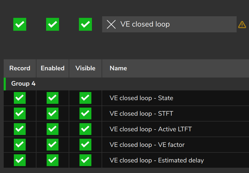
On the FT470, before running, raise the Sampling rate to 100 Hz and mark Enabled and Visible on these channels. On the FT700, mark Visible on the ones you will use:
- VE - O2 closed loop target and Lambda error (O2 sensor vs target)
- VE - Efficiency %, VE - Effective efficiency % and VE - Total enrichment
- VE closed loop - State, VE closed loop - STFT, VE closed loop - Active LTFT, VE closed loop - VE factor and VE closed loop - Estimated delay
- Primary injectors deadtime and Differential fuel pressure
Closed Loop / VE Probe, Engine RPM, MAP, TPS, Battery voltage, Injection time A, Engine temperature, Air temperature - intake and Fuel pressure are already among the 48 channels of the FT470 and come visible on the FT700.
When opening a log, FuelTech Vision turns off by itself every channel that stayed at zero from start to end, such as VE closed loop - Active LTFT with the LTFT not applied.
If a channel does not appear, look for it in Search channel and enable it.
#The VE channels
| Channel (as in the log) | Unit | What it shows | When it is zero or stuck |
|---|---|---|---|
| VE - Efficiency % | % | VE from the table at the current RPM and MAP, before the loop correction | Outside VE mode it is not published |
| VE - Effective efficiency % | % | VE used in the calculation: VE from the table × VE closed loop - VE factor | Outside VE mode it is not published |
| VE - O2 closed loop target | lambda | Target from the lambda target table, without subtracting enrichment | Outside VE mode it is not published |
| Closed Loop / VE Probe | lambda | Average of the O2 sensors marked in Sensor selection for average value; it is the O2 sensor that the loop reads | 0 when no marked O2 sensor has a valid reading |
| Lambda error (O2 sensor vs target) | % | Difference between O2 sensor and target at the same instant | 0 when the O2 sensor has no valid reading: a zero alone does not prove the tune is right |
| VE - Total enrichment | % | Sum of the VE mode enrichments: acceleration, post-start, engine temperature, gear and event compensations; it does not include the bank compensation | 0 with none of these terms active |
| VE closed loop - State | number | Why the loop corrects, freezes or learns (table further on) | Always published |
| VE closed loop - STFT | % | Fast correction that the loop is applying | 0 with the loop off |
| VE closed loop - Active LTFT | % | Learning applied at the current position | 0 with Apply the learned LTFT off, which is the default |
| VE closed loop - VE factor | factor | Total correction that multiplies the VE from the table | 1.000 with the loop off |
| VE closed loop - Estimated delay | ms | Estimated time between the injection and the O2 sensor reading | Loop off: does not change (stays at Maximum delay considered if it was already off when the VCU was turned on). Engine stopped or all injection cut: goes to that maximum |
| Injection time A | ms | Pulse of bank A, already with deadtime and enrichments | 0 with the engine stopped or with all injection cut |
| Primary injectors deadtime | ms | Deadtime of bank A, from the battery voltage and the differential pressure | 0 with the bank off |
| Differential fuel pressure (the screen shows Base fuel pressure) | bar | Fuel pressure (low-pressure line) minus the MAP | With Use fuel pressure sensor off, it stays fixed at the failsafe |
| VE total flow | l/min | Fuel flow calculated by the model; basis of the VE closed loop - Estimated delay | 0 with the engine stopped or with all injection cut |
Other channels appear in the log and confuse whoever reads the VE:
| Channel | What to know |
|---|---|
| MAP | Gauge pressure, in bar, as the screen shows it: vacuum is negative. It is one of the VE axes. |
| Air temperature - intake | It enters the calculation. With the sensor failed or off, the VCU uses the failsafe and this channel does not show that. |
| Fuel temperature | It appears in the log, but does not enter the VE calculation. |
| Acceleration fuel enrichment and decay | The value is in ms, but the channel does not show a unit. If it appears rounded, increase the channel Decimal places. |
| O2 target | In VE mode it repeats the VE - O2 closed loop target and is already on the same scale as the O2 sensor. |
| O2 average value and O2 closed loop correction | They belong to the pulsewidth mode. In VE mode they stay at 0: the VE correction is in VE closed loop - STFT and VE closed loop - Active LTFT. |
| Injection time Cylinder 01 - A and following | They include the individual cylinder trim and the linearization, which Injection time A does not include. |
| VE power and VE torque | Estimates from the fuel flow, not measured. |
| Active cut (ign) | The value 15 is the 4000 rpm limiter of VE mode for an external MAP sensor failure, with Use MAP sensor on, and it only appears while it is cutting. |
| Generic Channel 0 to Generic Channel F | They carry no VE loop data. With electronic throttle configured, the VCU occupies them: do not use them as a CAN destination or for a custom function. |
#Sign: which way each channel points
Lambda error (O2 sensor vs target) positive: the O2 sensor is leaner than the target. Negative: richer.
VE closed loop - STFT positive: the VCU is adding fuel. Negative: it is removing. A positive error (lean) pulls the STFT positive.
VE closed loop - VE factor at 1.000 means no correction; 1.050 is 5% more fuel; 0.950 is 5% less.
Lambda error (%) = (O2 sensor − target) ÷ target × 100
VE factor        = (1 + active LTFT ÷ 100) × (1 + STFT ÷ 100)
effective VE     = VE from the table × VE factor
The VE closed loop - VE factor does not go beyond the Total authority (STFT + LTFT) (default 25%: from 0.750 to 1.250); at that limit it stops and the formula above can go past it.
To check a log: VE - Effective efficiency % divided by VE - Efficiency % must give the VE closed loop - VE factor.
With the loop on and the factory defaults, it learns without applying: VE closed loop - Active LTFT stays at 0.0% and the STFT carries the whole correction: the zero does not prove that nothing was learned, and what was learned only appears on the live VE learning (LTFT) screen, with the VCU connected.
#Log target and table target
VE - O2 closed loop target is the lambda that the target table asks for at the point (for example 0.85), not an AFR. With flex, it already includes the target correction for the ethanol blend.
It does not subtract any compensation: post-start, engine temperature, acceleration fuel enrichment, gear, air conditioning, fan and the other terms of VE - Total enrichment stay outside the target.
While VE - Total enrichment is different from zero, the Lambda error (O2 sensor vs target) adds up two things: the VE error and the enrichment.
To judge the VE, use segments with VE - Total enrichment at zero, or subtract the enrichment with the required VE calculation, further on.
With the loop on, leave the steady-state compensations at zero in the range where it acts: the reason is in Enrichments and compensations in VE mode.
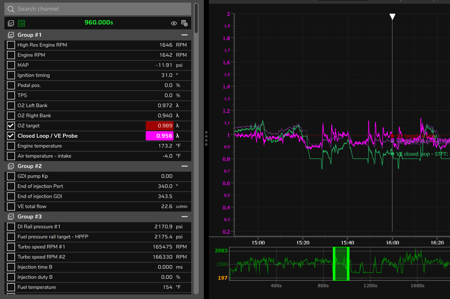
By default the target comes with a scale of 0 to 29.4 and the O2 sensor, from 0 to 2: the target trace is flattened. Put both on the same scale, or use the O2 target.
The Lambda error (O2 sensor vs target) compares the O2 sensor with the target of the same instant, with no dead band.
The loop compares the O2 sensor with the target delayed by the VE closed loop - Estimated delay (the new target enters gradually, over that time) and ignores an error smaller than the Lambda error dead band. When the target changes, the two disagree.
#The O2 sensor delay
The O2 sensor reads what was injected a little earlier: the gas takes time to reach it and the O2 sensor takes time to respond.
The VCU estimates this time at every instant and records it in VE closed loop - Estimated delay. It is an estimate, not a measurement.
In an RPM, MAP or TPS ramp, comparing the O2 sensor and the target at the same instant shows an error that does not exist.
To read the VE, use only steady-state segments (steady pedal and MAP, as defined in Step-by-step tuning method) and only start counting after the time of VE closed loop - Estimated delay has passed since the start of the segment.
The loop itself does the same: it does not learn in a transient or with the target moving, and waits out the delay before going back (states 9, 10 and 13).
The channel table above shows when the channel stays stuck; the typical values and where the calculation comes from are in VE closed loop.
#Loop and learning states
The VE closed loop - State channel records a number. The live VE learning (LTFT) screen shows the same state as text.
When there is more than one reason at the same time, the channel shows only one. Resolve the one that appears and check again.
In the Correction column: zeroes, the STFT goes to zero (immediately with the loop off); drops, the STFT goes down in a ramp to zero; freezes, the STFT stays fixed; corrects, the STFT keeps acting.
Only in states 14 and 22 can the LTFT learn.
| No. | Text on the screen | Correction | When it appears (factory values) |
|---|---|---|---|
| 0 | Disabled | zeroes | Loop off, engine stopped, start or during post-start |
| 1 | O2 sensor failure | drops | O2 sensor without a valid reading or stuck, or invalid target |
| 2 | O2 sensor heating | freezes | Some O2 sensor in the average still warming up |
| 3 | Cold engine | freezes | Engine below the Minimum engine temperature (70 °C) or temperature sensor failure |
| 4 | Post start | zeroes | Up to 15 s after the end of the post-start (Time after start to begin) |
| 5 | Out of RPM range | zeroes below, freezes above | Outside Minimum RPM (500 rpm) to Maximum RPM (8000 rpm) |
| 6 | Fuel injection cut | freezes | During injection cut, including on a gear change with cut |
| 7 | Launch / ALS / pit limit | freezes | Launch, anti-lag (ALS) or pit limit active |
| 8 | Enrichment active | freezes | Acceleration fuel enrichment active (by default, any value) or bank compensation different from zero |
| 9 | Transient | freezes | TPS varied more than 5% or MAP more than 0.05 bar in the recent window, of one to two times (one delay plus 0.3 s) |
| 10 | Target moving | corrects | The current target differs from the delayed target that the loop uses by more than 0.007 |
| 11 | Injectors saturated | freezes | Pulse plus deadtime fills the whole cycle |
| No. | Text on the screen | Correction | When it appears (factory values) |
|---|---|---|---|
| 12 | Test mode | freezes | Test mode or compression test active |
| 13 | Waiting to stabilize | freezes | One delay plus 0.3 s after one of the states 1 to 8, 11 or 12 ends; at least 2 s after a cut |
| 14 | Total authority reached | corrects at the limit | VE factor reached the Total authority (STFT + LTFT) (25%); the LTFT can still learn |
| 15 | STFT saturated (VE probably wrong) | corrects at the limit | STFT at the limit for more than 30 s: the VE needs more correction than the loop can give |
| 16 | VE model sensor in failsafe | corrects | Use MAP sensor off or MAP invalid; air temperature or fuel pressure invalid with their Use ... sensor option on |
| 17 | Fuel pressure out of range | corrects | Only with Use fuel pressure sensor on: differential pressure more than 10% away from the rated pressure of the injectors of the first enabled bank that is not direct injection |
| 18 | Air temperature out of range | corrects | Intake air outside 15 to 45 °C |
| 19 | Ethanol changing | corrects | Ethanol varied more than 2% in 10 s |
| 20 | Battery voltage out of range | corrects | Battery below 10.5 V or above 15 V |
| 21 | Correcting (waiting for cell to stabilize) | corrects | Normal state at steady state, while the STFT does not yet ask for a transfer to the LTFT |
| 22 | Learning | corrects | Only at the instant when part of the STFT passes to the LTFT |
| 23 | Correcting (waiting for acceleration fuel enrichment to end) | corrects | Does not appear with the factory default |
At steady state, with the loop correcting, the normal thing is to see state 21.
State 13, Waiting to stabilize, is the wait after a lockout, with the correction frozen: do not confuse it with state 21, in which the loop corrects.
State 14 has high priority and hides states 10 and 15 to 23 that are active at the same time.
State 22 lasts only an instant at each transfer, which happens after 4 s with STFT of at least 1.5%, positive or negative, in the same region: the log may not record it.
With the factory values, from 1.0 bar up the LTFT does not learn, even if the state passes through 22. With Long term learning (LTFT) off, 22 appears without anything being learned.
In state 16, check the Use ... sensor options: they are on by default, and the one for the sensor the car does not have must be turned off (see Before you start: engine, fuel, injectors and sensors).
The lockouts active at the same time and the cell that is learning appear only on the live screen (see Self-learning: VE learning (LTFT)).
#Recommended log screen for tuning VE
Build five groups, in this order, from Group #1 to Group #5, and save with Build a preset to use again in other logs.
On the FT470, also enable Acceleration fuel enrichment and decay, VE total flow and, with flex, FlexFuel: Ethanol %: they are not among the 48 channels of the new map.
| Group | Channels | What for |
|---|---|---|
| 1 Where the engine is | Engine RPM, MAP, TPS, Air temperature - intake, Engine temperature, Battery voltage | VE axes, transient and lockout reasons |
| 2 Mixture | Closed Loop / VE Probe, VE - O2 closed loop target, Lambda error (O2 sensor vs target), VE - Total enrichment | Mixture error and how much of it is enrichment |
| 3 Loop | VE closed loop - STFT, VE closed loop - Active LTFT, VE closed loop - VE factor, VE closed loop - State, VE closed loop - Estimated delay | What the loop did and why |
| 4 VE and pulse | VE - Efficiency %, VE - Effective efficiency %, Injection time A, Primary injectors deadtime, Injection duty A, Differential fuel pressure | VE used, pulse, deadtime and injector headroom |
| 5 Context | Active cut (inj), Active cut (ign), Acceleration fuel enrichment and decay, VE total flow, FlexFuel: Ethanol % (with flex) | Cuts, transient and basis of the delay |
Put O2 sensor and target on the same scale, for example 0.70 to 1.30. For Lambda error (O2 sensor vs target) and VE closed loop - STFT, −15 to 15; for VE closed loop - VE factor, 0.85 to 1.15. The scale is adjusted in the channel Advanced settings (Ctrl + right-click on the channel), in the Minimum and Maximum fields.
#The range of the VE - Efficiency % channel
The VE value has no ceiling: the VCU calculates it, the log records it and the log file stores 130% as 130%.
What can cut it is the drawing: the chart goes from the Minimum to the Maximum of the channel scale, and the trace above the Maximum is cut off at the top of the chart, or of the group range; if the trace seems to have a ceiling, check the Maximum. The number in the channel list stays right: when in doubt, read the number, not the height of the line.
In a new map, VE - Efficiency % comes with a scale of 0 to 179% and Fix scales checked. In a map created by an earlier software version, check the Maximum.
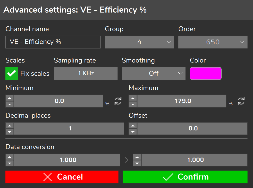
If you uncheck Fix scales, the scale goes back to 0 to 100%, and a VE above 100% sits above the Maximum.
If your table has VE above the Maximum, leave Fix scales checked and put the Maximum above the highest value in the table (the VE table goes up to 300%). VE - Effective efficiency % comes hidden, with a scale of 0 to 200%.
In the Dashboard, a graphic VE gauge comes in with Maximum 100, and needle, bar and arc stop there. Change the Maximum or use the digital gauge, which writes the real number.
#Calculated channels
The viewer creates calculated channels on the computer, from the samples of a log already recorded.
Use Create new channel, give it a name and build the formula in Expression, clicking on the Channels and the Operations. The formula accepts the four operations, power and parentheses, with normal precedence.
Except for the integral and the derivative, the channel combines values of the same instant: there is no shift in time, comparison or condition.
The mixture error does not need a calculated channel: it is already the Lambda error (O2 sensor vs target).
#Required VE
required VE = effective VE × O2 sensor ÷ target × (1 + enrichment ÷ 100)Effective VE is VE - Effective efficiency %; O2 sensor, Closed Loop / VE Probe; target, VE - O2 closed loop target; enrichment, VE - Total enrichment.
The result is the VE, in %, that would make the model match the engine at that instant, with the enrichment subtracted.
Example: effective VE 80%, O2 sensor 0.90, target 0.85 and enrichment 10% give a required VE of 93.18%.
The calculation is valid for segments with no bank compensation and no individual cylinder trim acting; in direct injection, also without the fuel pressure compensation.
#Deadtime fraction and useful time
Deadtime fraction (%) = Primary injectors deadtime ÷ Injection time A × 100
Useful time (ms)       = Injection time A − Primary injectors deadtime
The fraction shows how much of the bank A pulse is deadtime. Where to use this number is in Step-by-step tuning method.
#Care with the calculated channel
- In AFR, the required VE comes out multiplied by the stoichiometric AFR of the fuel.
- Build the expression with the buttons. If you type it, leave a space before and after each operator and use a period as the decimal separator.
- If the channel disappears when you open the log, one of the channels in the expression was not recorded or stayed at zero for the whole log. The common case is VE - Total enrichment: remove the term (1 + enrichment ÷ 100), which in that log is worth 1.
- The channel belongs to the log in which it was created: neither the preset nor Apply settings to the map takes it to another log. Create it again in each log.
- Export to CSV does not include the calculated channel.
- The new channel comes with a very wide scale: adjust Minimum and Maximum to see the trace.
#Reading the error per cell
The ready-made error-per-cell table exists live, on the VE learning (LTFT) screen, with the VCU connected (see Self-learning: VE learning (LTFT)).
FuelTech Vision does not build this table from a recorded log. In the log, the per-cell calculation is done with the Overlay, the calculated channel and the Average between cursors:.
The Overlay opens with the Overlay button of the chart and shows a cross on the VE table at the RPM and MAP of the cursor instant, between cells when the point is between them.
It uses the map that is open in FuelTech Vision, which may not be the one from the log.
- Open the log and the map that ran in it, with Open map from log. Without an open map, the Overlay offers to open the one from the log.
- Check that the map O2 sensor unit is in lambda and create the required VE channel.
- Turn on the Overlay, choose Engine tune and the VE table, and turn on Follow RealTime so the table follows the cross.
- Find a segment with RPM, MAP and TPS steady, VE - Total enrichment near zero and the cross stopped near the center of a cell.
- Right-click the chart and, in Cursors, use Set cursor 1 at the start of the segment plus the time of VE closed loop - Estimated delay, and Set cursor 2 at the end.
- In Average between cursors:, check whether the required VE appears and read its average; if it does not appear, use there the averages of O2 sensor, target, effective VE and enrichment in the same formula. Compare with the cell.
- To correct in the Overlay, confirm the change in the panel: it takes effect when you save or send the map.
Near the edge of the cell, the VE used is the blend of four cells: the average corrects the point, not the cell. That is why the cross must be near the center.
For many cells at once, use Export to CSV with RPM, MAP, O2 sensor, target, effective VE and enrichment, group them in a spreadsheet and redo the calculation there.