6. The tables: VE, lambda target, axes and grids
In VE mode, the VCU reads three tables: the volumetric efficiency one, the lambda target one and, when the manifold pressure reading is missing and the MAP failsafe is set to table (the default), the estimated MAP one. The calculation that turns these values into injection time is in How the VCU calculates fuel in VE mode.
#Where the tables are
All three are in the Fuel tables menu and open in the same table editor.
| Screen | What it stores | Axes | Maximum size |
|---|---|---|---|
| Main MAP VE table | Volumetric efficiency, in % | RPM × manifold pressure | 32 × 32 |
| Lambda target table by MAP | The lambda you ask for | RPM × manifold pressure | 32 × 32 |
| MAP estimated by TPS | Estimated manifold pressure, in bar | RPM × throttle position (%) | 16 × 16 |
The first two only appear with Fuel strategy at VE Based (Engine Settings > Engine settings); the third, only in VE mode and with MAP failsafe at MAP estimated by TPS table.
The tables of pulsewidth mode stay stored in the file. What happens when you change the strategy is in From the pulsewidth map to VE.
#The VE table
The Main MAP VE table stores the engine's volumetric efficiency, in %, for each engine speed and manifold pressure point. On the screen, the engine speed is in the columns and the pressure in the rows; Switch axis, in the right-click menu on the table, reverses that layout only in how it is shown, and the choice is saved in the map.
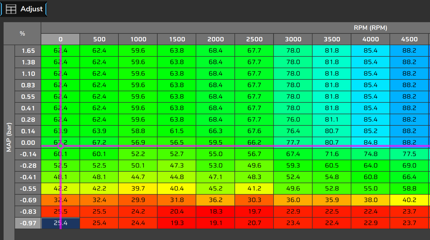
There is a single VE table for the whole engine. Banks A, B and C use the same VE; what changes from one bank to another is the injector.
There is no second table per fuel and no table selector. Flex changes the properties of the fuel, not the table: see Before you start: engine, fuel, injectors and sensors.
| Item | Value |
|---|---|
| Range of each cell | 0 to 300%, with one decimal place (the + key raises 0.5%) |
| RPM axis | 0 to 16000 rpm |
| Pressure axis | −1.00 to +20.00 bar, gauge |
| Size | up to 32 rows x 32 columns |
| Factory default | 22 engine speeds (0 to 8500 rpm) x 28 pressures (−1.0 to +3.4 bar) |
The factory default is a generic table: it goes from 20.8% (0 rpm, −1.0 bar) to 104.1% (5000 rpm, from +1.0 bar up) and is flat above +1.0 bar at each engine speed.
It was not made for your engine: how to get to the VE of your engine is in From the pulsewidth map to VE.
The load axis of the VE is always the manifold pressure. The Main fuel table field, in Engine settings, does not change that; even so, keep it at Boost in VE mode, except on individual throttle bodies when you want ignition by throttle (see What makes VE advanced, and the limits). At TPS, the log overlay (the Overlay button on the chart) shows a throttle-based VE table that the VCU does not use, with the cursor at the throttle position (see Reading the log: the VE channels).
The closed loop does not alter the table: it corrects the fuel from the outside. The table only changes when you edit it or apply the learning (see VE closed loop and Self-learning: VE learning (LTFT)).
#Pressure on the axis: gauge
The pressure axis of the VE tables is in gauge bar, as the MAP appears on the screen: negative is vacuum, positive is boost. For the calculation, the VCU adds a fixed 1.01325 bar and arrives at the absolute pressure (see How the VCU calculates fuel in VE mode).
In Measurement units > Pressure you choose bar (default), psi or kPa. The change only multiplies (× 14.5038 for psi, × 100 for kPa), without adding anything.
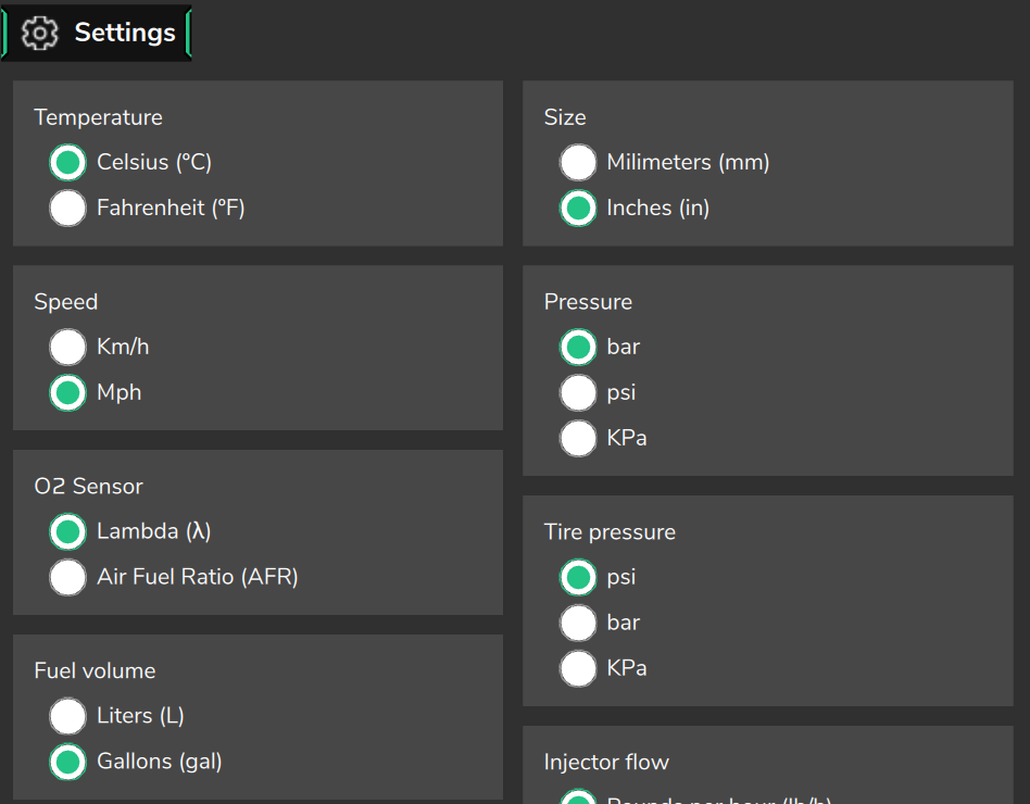
For that reason the kPa on the screen is also gauge: 100 kPa on the screen is 1 bar of boost, not the absolute pressure.
If your reference uses absolute kPa, convert like this:
gauge bar = absolute kPa ÷ 100 − 1.01325Example: 30 kPa absolute becomes −0.71 gauge bar; 250 kPa absolute becomes +1.49 gauge bar.
What this changes at altitude is in What makes VE advanced, and the limits.
#Between points and outside the table
Between points, the VCU interpolates among the four neighboring cells, by engine speed and by pressure.
Outside the table, it does not extrapolate. Below the first point or above the last, it repeats the edge value.
This holds for the three VE tables and for both axes of each one.
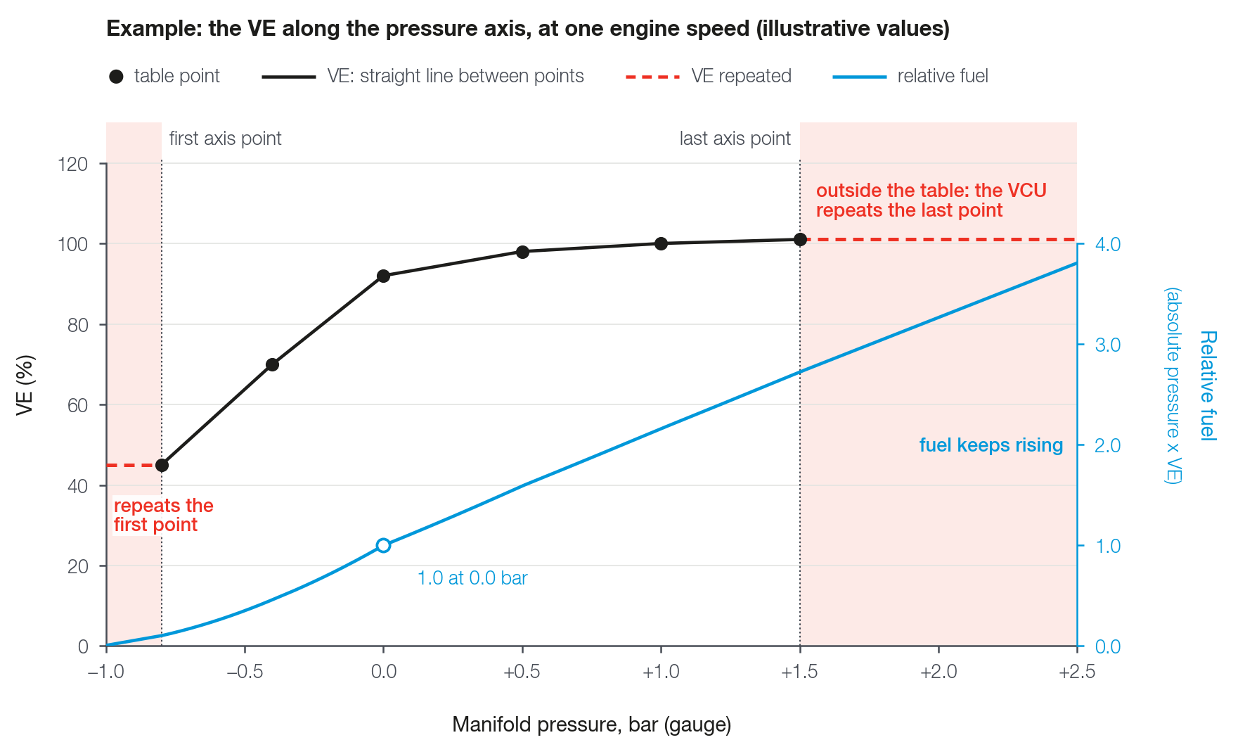
If the turbo goes past the last point of the pressure axis, the engine runs with the VE of that point, whatever the pressure. The fuel still grows above the edge, because the absolute pressure multiplies the calculation: what stays fixed is only the VE.
A cell that the engine has never visited should not be leaner than the measured neighbor: see Step-by-step tuning method.
#The lambda target
The Lambda target table by MAP stores the lambda you want at each engine speed and manifold pressure point.
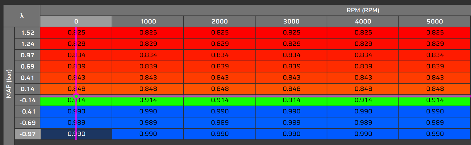
Range: lambda 0.28 to 10.00, with three decimal places (the + key raises 0.01). Size: up to 32 × 32.
The VCU reads the target at the same engine speed and pressure point at which it reads the VE, including when the pressure comes from the estimated MAP.
The target has its own axes: its grid does not need to be equal to the VE's.
The factory default has 25 engine speeds (0 to 8500 rpm) x 32 pressures (−1.0 to +6.0 bar) and the same value at all engine speeds:
| Manifold pressure (bar, gauge) | Lambda target |
|---|---|
| −1.0 to −0.6 | 0.950 |
| −0.5 | 0.933 |
| −0.4 | 0.917 |
| −0.3 | 0.900 |
| −0.2 | 0.883 |
| −0.1 | 0.867 |
| 0.0 | 0.850 |
| +3.0 | 0.800 |
| +6.0 | 0.780 |
Between 0.0 and +3.0 bar, and between +3.0 and +6.0 bar, the default goes down gradually. It is a generic starting point: the target for your engine is your decision.
The enrichments add fuel without moving the target. A mixture that is different on purpose, such as richer at high load, is requested in the target: see Enrichments and compensations in VE mode.
With flex, the VCU can shift the target according to the ethanol content: see Before you start: engine, fuel, injectors and sensors.
#Lambda or AFR on screen
In Measurement units > O2 Sensor you choose to see the target and the O2 sensors in lambda or in AFR.
The VCU stores and uses the target in lambda. AFR is just the way of displaying it.
In AFR, the screen multiplies the lambda by the stoichiometric AFR of the fuel configured in the map: lambda 0.85 with a stoichiometric AFR of 14.7 appears as about 12.5.
Prefer lambda. In AFR, the same lambda appears with different numbers for each fuel; with flex, always use lambda.
#Recommended grid
The VCU accepts up to 32 × 32 points in the VE and in the target. A map opened with more points is cut by FuelTech Vision, with the warning Map adjusted: the first 32 points of each axis stay, and the ones with higher engine speed and pressure are dropped.
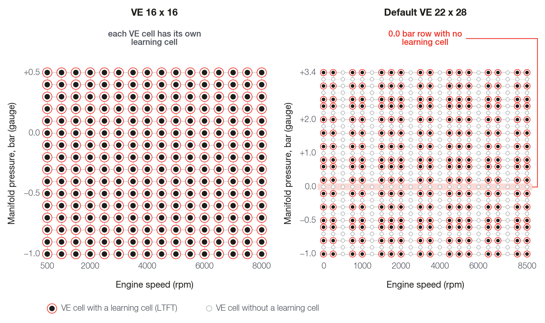
For the VE, we recommend up to 16 × 16. The reason is the long term learning (LTFT): its table has at most 16 × 16, with the axes copied from the VE axes at the moment the learning is cleared.
With up to 16 points per axis, each VE cell has its own learning cell; with more, the learning takes 16 spaced points and learns coarser than the table (see Self-learning: VE learning (LTFT)).
The factory default of the VE, 22 engine speed points × 28 pressure points, is in that situation: the learning skips, for example, the 0.0 and +1.0 bar rows.
For the target, the VCU does not ask for a special size, and the learning does not use its grid. As a rule of thumb, we recommend 10 × 10 for the target: there are fewer cells to keep consistent, and the target does not need the resolution of the learning.
In both tables, use axes with equal steps: for example, 500 to 8000 rpm in steps of 500 rpm gives 16 points.
The reason is the editor's Smooth: it works by the position of the cells, not by the axis value. With an equal step, position and value go together.
#Changing the axes
In the editor, Edit axis opens the Edit axis window.
In it you edit the axis values or generate a sequence with Generate values: Initial value, Final value, Increment and the option Replace existing values.
When you change the axis values, FuelTech Vision resamples the table and keeps the shape of the curve. A new point outside the old range receives the edge value, not a measured value: check these points after resampling.
The editor refuses a repeated value on the axis (Value already exists) and warns when the cell limit is exceeded (Limit exceeded).
You can also add and remove points with Add row, Remove row, Add column and Remove column, up to 32 per axis in the VE and in the target.
If the start of any bank uses the Fuel injection main table, the lowest engine speed columns give the fuel for the cranking speed. Check them too (see Enrichments and compensations in VE mode).
Changing the VE axes does not change the learning axes, which stay on the old grid until cleared. Before changing the axes, take the useful learning to the VE; after sending the map, use Clear LTFT. The complete order and the reason are in Self-learning: VE learning (LTFT).
#The editor during tuning
The operations apply to the selected cells. The keys are those of FuelTech Vision on the computer.
| Operation | Key | What it does |
|---|---|---|
| Increase value and Decrease value | + and - | One step up or down; with Shift, the smallest step; with Ctrl, 10 steps |
| Add | A | Adds a value to the cells |
| Multiply | M | Multiplies by a factor: 1.05 raises 5% |
| Fill | Space | Opens the keypad to type the value of the cells |
| Copy and Paste | Ctrl+C and Ctrl+V | Copies and pastes blocks of cells |
| Select all | Ctrl+A | Selects the whole table |
| Interpolate | I | Draws a straight line between the first and the last cell, by axis value |
| Interpolate Horizontal | H | The same, only in the horizontal direction |
| Interpolate Vertical | V | The same, only in the vertical direction |
| Smooth | S | Smooths by the position of the cells; requires 2 or more rows and 2 or more columns |
Interpolate respects the axis value: with unevenly spaced points, the line comes out right.
Smooth ignores the axis value and acts on the whole rectangle that goes from the first to the last selected cell, including the unselected ones inside it.
Each operation on several cells is undone at once, in full.
#With the VCU connected
With the VCU connected, the cursor of the active cell shows the point where the engine is. On the VE and on the target it follows the engine speed and the pressure from the sensor; on the estimated MAP, the engine speed and the throttle.
Show trail shows the last seconds of the path of the cursor.
Show heat map highlights the cells around the current point. It does not count how long the engine spent in each cell.
Automatic selection automatically selects the block of cells under the current point while the engine moves.
On the VE there is no Apply correction in the active cell (F): the button disappears and the menu item is disabled.
The correction comes from the learning (LTFT), and taking it to the table is a step of yours: VE learning (LTFT) (on the computer, Tools menu), Commit to VE page (the one that takes the learning to the VE table), Preview and Apply to VE buttons. See Self-learning: VE learning (LTFT).
The real-time bar of these screens shows O2 closed loop correction. In VE mode, this number is not the correction of the VE loop: for that, use the VE loop channels (see Reading the log: the VE channels).
How the edit of a cell reaches the VCU is in Before you start: engine, fuel, injectors and sensors.
#MAP estimated by TPS
The pressure on the axis comes from the MAP sensor. It passes to the failsafe (by default, the estimate by TPS) in two cases: Use MAP sensor off, or an external MAP sensor (or the backup one) in failure.
The MAP failsafe field, in Engine Settings > Fuel injection > Sensors and failsafe tab (only in VE mode), chooses between MAP estimated by TPS table (default) and Fixed value, which uses the value of Manifold pressure failsafe (default −0.30 bar, range −2.00 to +20.00 bar).
The MAP estimated by TPS table stores, in gauge bar, the manifold pressure expected for each engine speed and throttle position.
The factory default is for a generic naturally aspirated engine: 500 to 8000 rpm x throttle from 0 to 100%, with −0.80 bar at closed throttle and near 0 bar at wide-open throttle.
It estimates slightly above what is expected, toward the rich side, and never goes above 0 bar.
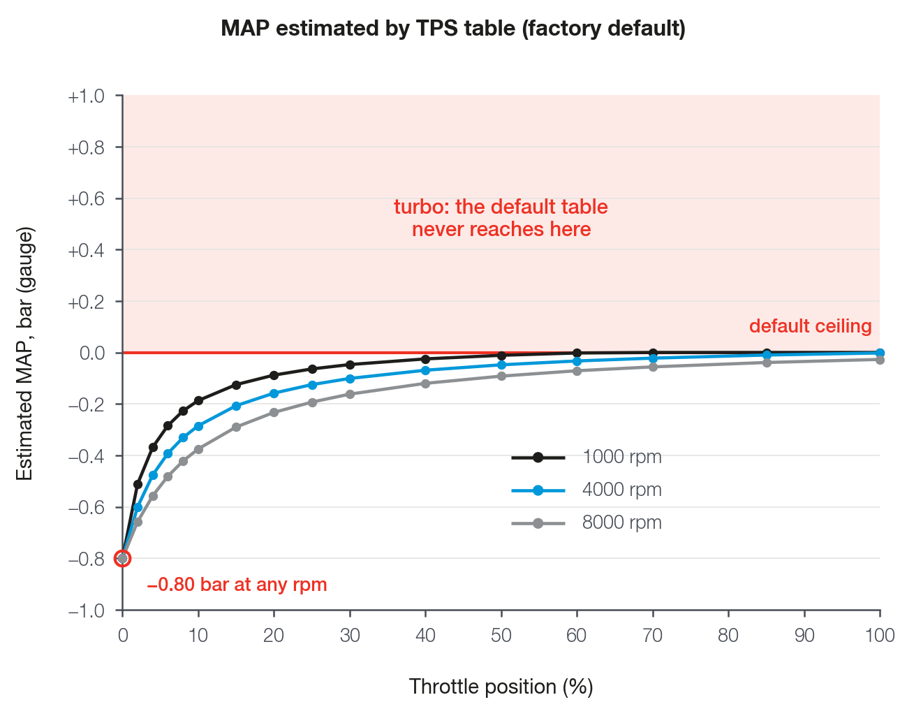
The screen accepts values from −1.000 to +6.000 bar, and the VCU uses what is in the table, with no lock. The 0 bar ceiling belongs only to the default.
With the estimate active, the VCU reads the VE and the target at the estimated pressure. The MAP channel of the log and the table cursor keep showing the sensor; the estimated pressure does not appear in any channel.
The default table is for a naturally aspirated engine (it does not go above 0 bar): see the warning about turbo engines in Before you start: engine, fuel, injectors and sensors, where the 4000 rpm MAP failure limiter and what changes with the internal sensor are also described.
With Use MAP sensor off, the learning of the VE loop is locked: see Self-learning: VE learning (LTFT).