2. How the VCU runs a custom function
#The 1 kHz loop
The VCU runs the entire graph every 1 ms (1 kHz). Each run is a cycle. The interval is nominal: the exact instant of each cycle depends on processor load. The size of the graph is limited by the two memory areas described below. After writing a function, confirm in the log that the VCU responds as before.
The cycle does not pass the time interval to the blocks. Each block uses its own time base:
| Time base | Blocks |
|---|---|
| Per step: 1 step is 1 cycle, about 1 ms | EMA filter (exponential moving average), Average filter, Counter, Sample and Hold (stores a value at the instant of a trigger); the internal filter of the Derivative |
| Real time, in milliseconds or by the interval measured by the VCU | Delay, Cyclic timer, Ramp, Low pass filter, Integrator, Derivative, decay of the Maximum value detector |
| Fixed scale of the Loop time (ms) field | PID (proportional, integral and derivative control): the field is not the period; the block runs every cycle |
#A single graph, in dependency order
The enabled functions of the map, up to 10, become one single graph. The VCU runs the blocks in dependency order: each block runs after all the blocks that feed it and reads their value from the current cycle, never from the previous cycle.
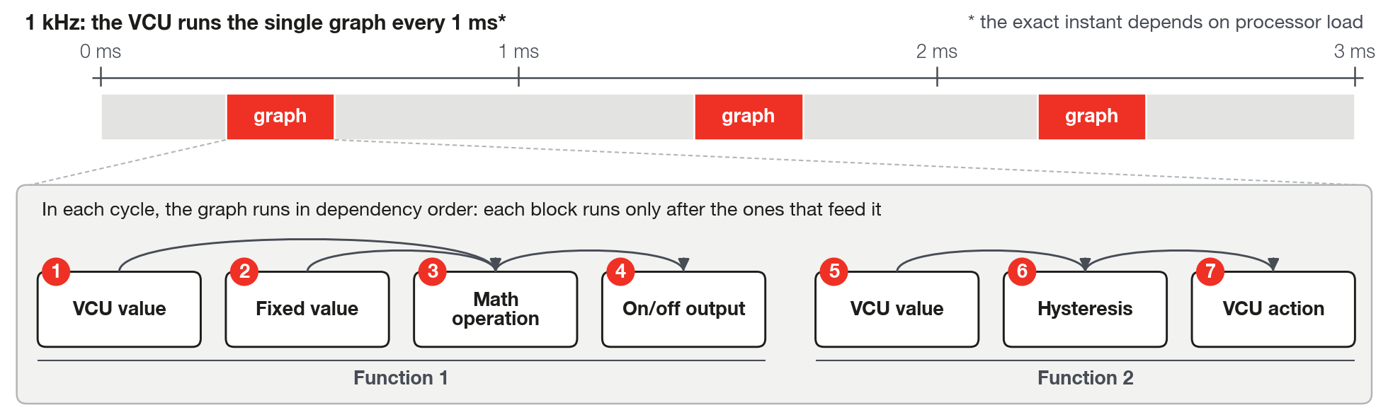
Different functions have no links between them. To pass a value from one function to another, write it with Value for VCU to a Custom measurement channel and read the same channel with VCU value in the other. Check in the log at what point the value arrives at the other function.
#Feedback loop in the graph
The editor lets you connect blocks in a circle, so that the result of one block returns, through other blocks, to an earlier input: a feedback loop. It only refuses a link from a block to itself and a second link on the same input. Do not confuse this feedback loop with the 1 kHz loop.
The VCU does not run a feedback loop. The blocks that are part of it, and all the ones that depend on them, never enter the execution order: the VCU does not run them and the memory meter keeps counting these blocks.
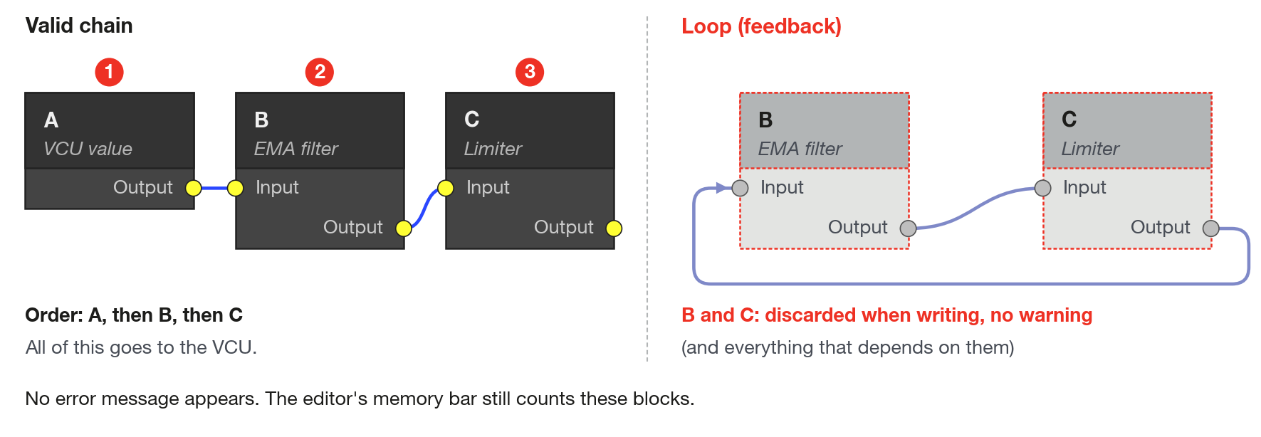
On the VCU, a block never reads the output of a block that runs after it. For the previous result to influence the next one, there are two ways. The first is to use a block that keeps state from one cycle to the next, such as Hysteresis, SR Latch (keeps a state between a Set command and a Reset command), Integrator or Counter: the stored value returns to 0 when the graph is loaded. The second is to pass the value through a free Custom measurement channel: Value for VCU writes and VCU value reads the same channel. A measurement that already comes from a physical input or from the CAN bus (the communication network between the vehicle's modules) can have its value overwritten. Check the delay between writing and reading in the log before relying on this path.
#Floating-point numbers
Every value that passes through a link is a number with decimal places, with about 7 digits of precision; the editor shows 6 decimal places. What this implies:
- A logic signal is the number 1.0 (true) or 0.0 (false).
- An input without a link is 0.0, not the last value. There are few exceptions, described in the block sheets.
- In the Logic block, an input is true when it is greater than 0.0: 0.3 is true; 0 and negative numbers are false. There is no 0.5 threshold. If you connect an analog signal directly to Logic, you will notice this; if you only use 0 and 1, you will not.
- A button arrives in the graph as 1.0 or 0.0. RPM and gear are integers on the VCU and arrive in the graph as integers, without scaling.
- The VCU does not check for or warn about an invalid result (NaN, short for "not a number", or infinity) or division by zero. The Math operation block returns 0 on a division by zero.
#Memory: two areas for the entire map
The VCU reserves two memory areas for custom functions. The limits apply to the entire map, not to each function: the use of all enabled functions is added up.
- Working memory, 512 bytes (the RAM bar): stores the state of each block, such as the output and the accumulators.
- Configuration, 2048 bytes (the Settings bar): stores the type of each block, the connections and the parameters.
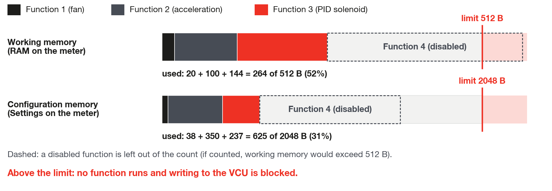
FuelTech Vision shows the usage in the lower left corner of the editor. The Memory: N% title shows the larger of the two percentages; the "used / total" numbers show the actual value (the colors and the 100% bar limit are in the chapter The Custom functions screen).
Enable and disable. Only enabled functions count toward memory and are run. A disabled function stays stored in the map, and its bytes become free again. If all functions are disabled, the VCU runs no graph. The chapter The Custom functions screen shows how to enable.
#What uses the most
Most blocks use 4 to 16 bytes of working memory. The blocks below use more:
| Block | Working memory (of 512 bytes) | Configuration (of 2048 bytes) |
|---|---|---|
| VCU action | 32 | 16 |
| Average filter (1 to 32 points) | 16 to 140 | 5 |
| Table 12x12 | 4 | 682 |
| Table 8x8 | 4 | 330 |
| Table 4x4 | 4 | 106 |
| Vector 1x16 | 4 | 136 |
| PID | 12 | 22 |
| VCU value | 4 | 4 |
#Going over the limit
Confirm is not blocked by memory use. When writing the open map to the VCU, FuelTech Vision checks the memory before sending: if the configuration goes over 2048 bytes or the working memory goes over 512 bytes, it does not write and shows the dialog Custom Functions memory exceeded: "The Custom Functions in this map exceed the available memory. Reduce the number of blocks/parameters and try writing again." This check happens on the Write button in the top bar (tooltip "Write VCU"), in any of the three write options. Make active, in the list of maps stored in the VCU, does not repeat it: it only activates a map that is already there.
If a map over the limit is activated on the VCU without having gone through this check, no custom function runs: there is no partial load. With working memory above 512 bytes, the VCU warns "Custom function: execution memory full". With configuration above 2048 bytes, the graph is discarded without warning.
#VCU actions: priority and coexistence with native functions
The VCU action block has 17 actions, besides None, and no priority field. In the action names, ETC is the electronic throttle control (drive-by-wire), Flex Fuel is the use of fuel with variable ethanol content, O2 (the lambda sensor) is the sensor that measures the mixture in the exhaust and EV is electric vehicle. Each type of action coexists with the native functions in a different way:
| Type | Examples | Coexistence with native functions |
|---|---|---|
| Compensation | Ignition compensation, Fuel injection compensation, ETC compensation, Torque target compensation (EV) | Adds to what the native functions already calculate. Several blocks of the same compensation add up. |
| Replacement | Ignition timing, ETC opening limit, Ethanol override (Flex Fuel), O2 closed loop target override, Torque target override (EV) | Replaces the native value at that point, with fixed priority. The highest priority wins. ETC opening limit scales the target instead of replacing it (the VCU action sheet). |
| Cut | Ignition cut, Fuel injection cut | Competes with the native cuts: the highest level wins. |
The custom function enters with a fixed priority that you cannot change. In ignition, it loses to the native launch functions (3-step, 2-step and burnout) and to the gear shift, and ties with anti-lag, which holds turbo pressure with the throttle closed. On the ETC opening limit, it loses, among others, to boost control by ETC. Native functions of lower priority lose to it. With the hard cut, the rev limiter, the function wins only in the fixed ignition timing that the limiter can apply: the limiter's cut keeps acting. The High resolution ignition cut block does not use this priority: it competes with traction control, 2-step, 3-step and burnout for the highest percentage. In a tie with anti-lag there is no guaranteed order: do not rely on either of the two and check in the log which one acts. Two blocks that request the same replacement action: only one counts, and the other does not act. The replacements stay active the whole time the function runs, even with the input at 0, including the Torque target override (EV); only the O2 closed loop target override depends on an input greater than 0.
#Initialization
When the VCU is powered on and at every map write, the VCU loads the graph:
- The working memory is cleared: every internal state restarts at 0, such as accumulators and the state of hysteresis blocks and latches.
- The output blocks and the VCU action block start off and begin to respond to the graph from the first cycle.
- While the VCU receives a new map, the graph is not run. It comes back after the reload.
- When the graph is unloaded (for example, in a map with all functions disabled), the actions stop acting, the On/Off and PWM outputs turn off, the analog outputs go to 0 V and the channels written by Value for VCU keep the last value.
#Values shown on the blocks in the editor
The values the editor shows in the blocks are calculated on the computer, not read from the VCU (section Live values on the blocks, in the chapter Building the graph). Use them to check the connections of the drawing, not the behavior over time: the simulation may differ from the VCU, mainly in the blocks that depend on time or keep state, such as the filters, the Counter, the Maximum value detector, Delay, Cyclic timer, Ramp, Integrator and Derivative. An EMA filter, for example, responds about 100 times slower in the editor than on the VCU.
To see what the VCU really calculated, write the value with Value for VCU to a Custom measurement channel and follow that channel. Almost all the examples in this guide do this. Check beforehand that the channel is in the log's channel list.