6. Time, filter, control and table blocks
All the blocks in this chapter, except the tables and vectors, are in the Logics menu. The tables and vectors are in Tables.
All of them run on every cycle of the function, nominally 1 ms (1 kHz): the interval depends on the processor load. Each run is a cycle. Each sheet gives inputs, output, screen fields, calculation rule and memory cost.
#Time and counting
#Delay
Delays the state change of an on/off signal. It does not delay an analog value.
| Item | Description |
|---|---|
| Inputs | Input: greater than 0 is on; 0 or less, off. Override time: connected and greater than 0, it applies in place of the field; unconnected, the field applies. |
| Output | Always 0 or 1, never the value of the input. |
| Mode | On-Delay: delays only the rise (from 0 to 1). Off-Delay: delays only the fall. Both: delays both. Default: On-Delay. |
| Delay time (s) | Default 1.0; the screen accepts from 0.001 to 60. Unit: seconds. |
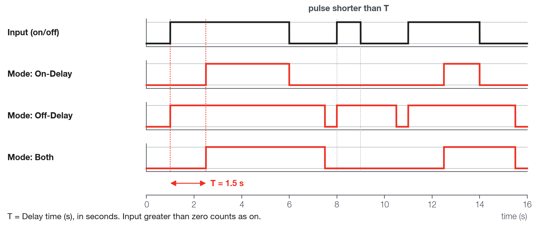
The output follows the input only after the new state has lasted the set time. In On-Delay, if the input returns to 0 before the time, the count is canceled. In Off-Delay, if it returns to 1, the output goes to 1 at once. In Both, each change restarts the count: a pulse shorter than the set time does not reach the output.
Memory: 16 bytes of working memory (map limit of 512) and 14 bytes of configuration (limit of 2048).
#Cyclic timer
Alternates endlessly between an on phase and an off phase and puts the value of the current phase on the output. It works as a pulse generator.
| Item | Description |
|---|---|
| Inputs | Data on: value that comes out in the on phase. Data off: value that comes out in the off phase. Unconnected, an input is 0. |
| Output | The value of Data on or of Data off. With 1 and 0 on the inputs it becomes a pulse train; with any two values, it alternates between them. |
| On time (ms) | Duration of the on phase. Default 1000; 0 to 999999. |
| Off time (ms) | Duration of the off phase. Default 1000; 0 to 999999. |
Period = On time + Off time. On fraction = On time ÷ (On time + Off time). There is no input to enable or to restart: the block runs from the moment the function is loaded. The count is in whole milliseconds: a fractional time counts as the next integer (7.14 becomes 8 ms) and 0 counts as 1 ms.
Memory: 12 bytes of working memory (map limit of 512) and 14 bytes of configuration (limit of 2048).
#Counter
Counts how many times the trigger rises. It saturates at the maximum: it does not return to zero by itself.
| Item | Description |
|---|---|
| Inputs | Trigger: each rise (from 0 or less to more than 0) counts 1. Reset: greater than 0 zeroes the output and blocks the count. Enable: unconnected, it enables; connected, it counts only if greater than 0. |
| Output | The current count. |
| Direction | Increasing adds 1 per rise; Decreasing subtracts 1. Default: Increasing. |
| Maximum count | Limit of the count, in absolute value. Default 9999; 0 to 999999. |
Increasing: rises up to the Maximum count and stays there. Decreasing: starts at 0 and falls to the negative value of the Maximum count; there is no adjustable initial value. Rises with Enable at 0 or with Reset high are lost. Releasing Reset with Trigger still high does not generate a count.
Memory: 8 bytes of working memory (map limit of 512) and 16 bytes of configuration (limit of 2048).
#Ramp
Takes the output from an initial value to a final value in a fixed time, when the trigger passes a limit.
| Item | Description |
|---|---|
| Inputs | Trigger value: the trigger. Initial value: where the ramp starts. Final value: where it ends. Unconnected, they are 0. |
| Output | Initial value while the ramp has not started; then the intermediate value; at the end, Final value. |
| Ramp time (ms) | Duration of the ramp. Default 1000; 0 to 999999. |
| Activate above: | The ramp starts when Trigger value becomes greater than this number. Default 0. |
| Rearm below: | After the ramp ends, it re-arms only when Trigger value becomes lower than this number; once re-armed, it restarts when the value is above Activate above:. Default 0. |
The ramp is defined by the duration, not by the rate: slope = (Final value − Initial value) ÷ Ramp time. Falling below Rearm below: in the middle of the ramp does not interrupt it. On re-arming, the output goes back at once to Initial value. Initial value and Final value are read on each cycle: changing them during the ramp bends the path.
Memory: 12 bytes of working memory (map limit of 512) and 20 bytes of configuration (limit of 2048).
#Sample and Hold
Stores the value of a signal at the instant a trigger changes and keeps that value on the output until the next trigger.
| Item | Description |
|---|---|
| Inputs | Signal: the value to store. Trigger: the trigger; greater than 0 counts as on. Unconnected, they are 0. |
| Output | The last value captured from Signal. It starts at 0. |
| Capture mode | Rising: the Trigger goes from off to on. Falling: the opposite. Both edges: both. Default: Rising. |
There is no reset input: the output changes only on a capture.
Memory: 8 bytes of working memory (map limit of 512) and 7 bytes of configuration (limit of 2048).
#Maximum value detector
Holds the largest (or the smallest) value seen at the input and, if you want, lets that peak decay with time.
| Item | Description |
|---|---|
| Inputs | Input: the signal. Reset: while greater than 0, the output copies the input on each cycle. Unconnected, they are 0. |
| Output | The held peak. |
| Mode | Maximum holds the largest value; Minimum, the smallest. Default: Maximum. |
| Decay rate | In signal units per second. Default 0 (the peak does not decay); 0 to 999999. |
With Decay rate greater than 0, the peak approaches the input in a straight line, by the measured real time, and never crosses it. Example: the peak was 1 and the input went back to 0; with rate 5, the output reaches 0 in 200 ms. On the first cycle after loading, the output starts from the value of the input, not from 0.
Memory: 12 bytes of working memory (map limit of 512) and 14 bytes of configuration (limit of 2048).
#Filters and derivative
Two of these blocks are set per 1 ms cycle (EMA filter and Average filter), one is set in hertz (Low pass filter), and the Derivative has a factor per cycle and an output in units per second. Each sheet says how to convert the setting to time or frequency. When the VCU is powered on and at every map write, the EMA filter and the Low pass filter start from 0 and take the filter time to reach the input, and the Derivative compares the first sample with 0, which gives a spike on the output.
#EMA filter
Smooths a signal by mixing the new sample with the previous value of the output.
| Item | Description |
|---|---|
| Inputs | Input: the signal. Unconnected, it is 0. |
| Output | The filtered signal. |
| Alpha | Weight of the new sample on each 1 ms cycle. Default 1.0 (no filter); 0 to 1 on the screen. |
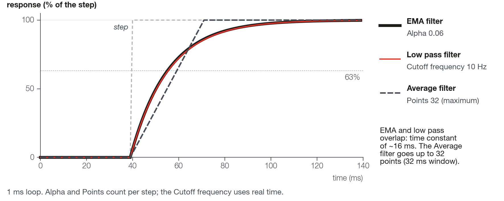
Output = Alpha × input + (1 − Alpha) × previous output. Alpha 1 passes the signal unfiltered; Alpha 0 lets no signal through. The Alpha is per cycle, not in time. The output reaches 63% of a step in 1 tau (the time constant of the filter) and 95% in 3 tau. Convert like this:
tau (ms) = −1 ÷ ln(1 − Alpha)
Alpha = 1 − e^(−1 ÷ tau)          (tau in ms)
cutoff frequency (Hz) ≈ 159 ÷ tau (ms)| Alpha | Time constant (tau) | Approximate cutoff |
|---|---|---|
| 0.005 | 199.5 ms | 0.8 Hz |
| 0.019 | 52.1 ms | 3.1 Hz |
| 0.05 | 19.5 ms | 8.2 Hz |
| 0.15 | 6.15 ms | 26 Hz |
| 0.5 | 1.44 ms | relation does not hold |
For tau = 50 ms, Alpha = 0.0198. The relation with the cutoff holds only for tau much greater than 1 ms.
Memory: 8 bytes of working memory (map limit of 512) and 8 bytes of configuration (limit of 2048).
#Average filter
Returns the average of the last N samples of the signal, one sample per 1 ms cycle.
| Item | Description |
|---|---|
| Inputs | Input: the signal. Unconnected, it is 0. |
| Output | The moving average. |
| Points | The number N of samples. Default 16; 1 to 32. |
With N points the window lasts N cycles (about N ms). For a step input, the output rises in a straight line and reaches the new value after N ms; for a ramp input, it lags (N − 1) ÷ 2 ms behind. Right after loading, while the samples do not fill the window, the average uses only the ones received.
Memory: 12 + 4 × Points bytes of working memory (map limit of 512) and 5 bytes of configuration (limit of 2048). It is the only block in the chapter with a variable cost. Examples: 16 B with 1 point, 44 B with 8, 76 B with 16 (default, 14.8% of the limit) and 140 B with 32 (27.3%).
#Low pass filter
First-order filter set by the cutoff frequency, in hertz, with the real time measured between cycles.
| Item | Description |
|---|---|
| Inputs | Input: the signal. Unconnected, it is 0. |
| Output | The filtered signal. |
| Cutoff frequency | In hertz. Default 100; 1 to 1000 on the screen. Value 0 or less: the signal passes unfiltered. |
| Q factor | Default 1.0; 0 to 1. It is not a quality factor: it mixes the filtered signal with the raw signal. 1 is filtered only. |
Time constant tau (ms) ≈ 159 ÷ Fc (Hz): 1 Hz gives 159 ms, 3 Hz gives 53 ms, 10 Hz gives 16 ms. At 1 kHz the filter stops making sense above 500 Hz. With Q factor below 1, the mix goes back inside the filter and it becomes faster than the cutoff indicates. Example with 10 Hz: Q 1 gives a tau of 16.4 ms; Q 0.99, 14.1 ms; Q 0.9, 6.0 ms; Q 0.5, 1.3 ms. Leave Q at 1 for the cutoff to hold.
Memory: 12 bytes of working memory (map limit of 512) and 12 bytes of configuration (limit of 2048).
#Derivative
Measures the rate of change of the signal, in units per second.
| Item | Description |
|---|---|
| Inputs | Input: the signal. Unconnected, it is 0. |
| Output | Change of the input per second, not per cycle. |
| Filter factor | Weight of the new sample (the screen writes the alpha symbol after the name) in the filter of the output, per 1 ms cycle. Default 0.5; 0 to 1. |
Derivative = (input − input of the previous cycle) ÷ time measured between the cycles (about 1 ms). With the filter factor (alpha) between 0 and 1, the output goes through a filter equal to that of the EMA filter: output = alpha × derivative + (1 − alpha) × previous output.
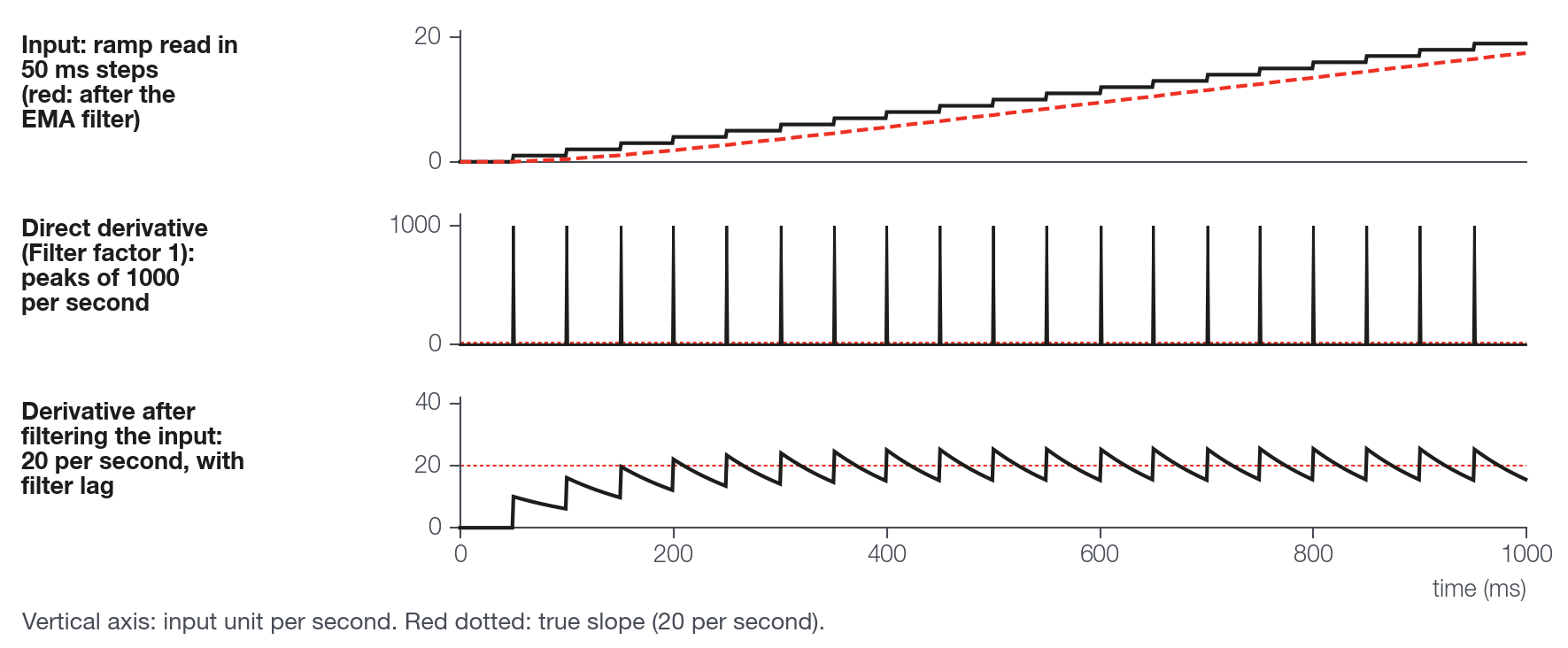
The derivative has no window: it compares two consecutive samples, about 1 ms apart. A signal that only updates now and then, in steps, gives derivative 0 on most cycles and a spike on the cycle in which the step arrives. Check in the log how often the channel changes. Filter before differentiating: the table shows a signal that rises 1 unit every 50 ms (real slope: 20 units per second).
| Setup | Lowest output (units/s) | Highest output (units/s) |
|---|---|---|
| Derivative with alpha 1 (no filter) | 0 | 1000 |
| Derivative with alpha 0.5 (default) | 0 | 500 |
| Derivative with alpha 0.05 | 4.4 | 54.2 |
| EMA filter (Alpha 0.0198) before, Derivative with alpha 1 | 11.8 | 31.3 |
| EMA filter (Alpha 0.0198) before, Derivative with alpha 0.05 | 16.3 | 22.1 |
Values calculated by the block formulas, with a 1 ms cycle, after steady state. The filter before costs delay: with a tau of 50 ms, the derivative arrives about 50 ms later.
Memory: 12 bytes of working memory (map limit of 512) and 8 bytes of configuration (limit of 2048).
#Which filter to use
| Situation | Block | Why | Working memory |
|---|---|---|---|
| You think in hertz | Low pass filter | The cutoff is in Hz, with the time measured between cycles. | 12 B |
| You think in response time and want the lowest cost | EMA filter | One calculation and one stored value; the Alpha is per cycle. | 8 B |
| You want a window of fixed size (N samples) | Average filter | The output reaches the new value in N ms, N cycles. | 12 + 4 × Points |
| You are going to differentiate a signal that changes in steps | One of the three, before the Derivative | The derivative without a filter turns into spikes. | (of the filter) |
#Control
#Integrator
Sums the input over time, with gain and limits.
| Item | Description |
|---|---|
| Inputs | Input: the value to integrate. Reset: while greater than 0, the output stays at 0. Unconnected, they are 0. |
| Output | The accumulated value. |
| Gain | Default 1.0; −999999 to 999999. Unit: per second. |
| Minimum limit | Floor of the accumulated value. Default −999999. |
| Maximum limit | Ceiling of the accumulated value. Default 999999. |
On each cycle: accumulated = accumulated + input × Gain × measured time (in seconds); then the accumulated value is limited between the two limits. Input 10 and Gain 1 for 2 s add 20. There is no fallback value: with the Input unconnected the block integrates 0 and the output does not move. There is no input to pause: to hold the value, take the input to 0 before the block (for example, with a Switch). The Reset zeroes without applying the limits. If Minimum limit is greater than Maximum limit, the minimum applies. In continuous use for hours, without reaching a limit, the accumulated value eventually stops growing for lack of numeric resolution.
Memory: 8 bytes of working memory (map limit of 512) and 18 bytes of configuration (limit of 2048).
#PID
Calculates an output from the difference between the measured value and the target, with proportional, integral and derivative terms.
| Item | Description |
|---|---|
| Inputs | Data (the measured value), Target, P gain, I gain, D gain (unconnected, it is 0) and Anti windup (optional: unconnected, the field applies). |
| Output | The sum of the three terms, with no limit. |
| Loop time (ms) | Time scale factor of the gains. Default 100; 1 to 999999. |
| Anti windup (fixed value) | Limit of the accumulated value, in absolute value (from −value to +value). Default 100; 0 to 999999. |
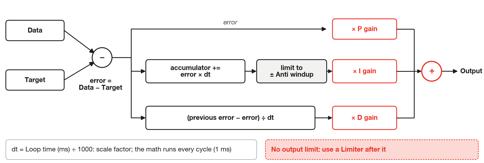
error = Data − Target
accumulated = accumulated + error × (Loop time ÷ 1000), limited to ± Anti windup
change = (previous error − error) ÷ (Loop time ÷ 1000)
Output = error × P gain + accumulated × I gain + change × D gain
The block runs on every cycle (nominally 1 ms). The Loop time (ms) does not change that: it enters only as the time of each calculation. Per second, the accumulated value grows error × Loop time, so the effective I gain is I gain × Loop time and the effective D gain is D gain ÷ Loop time. With Loop time at 1, the gains are in real units (I per second, D in seconds). With the default 100, an I gain of 0.5 yields 50. The three gains are inputs, not fields: connect a Fixed value to each.
The Anti windup limits the accumulated value before the gain: the integral term never exceeds |I gain| × Anti windup. There is no reset, enable or output limit: put a Limiter after the PID. The accumulated value sums all the time, even if you divert the output with a Switch, until it reaches ± Anti windup. The derivative term compares the error of two consecutive cycles (about 1 ms) and acts on the error, not only on the Data: data that changes in steps, a step in the Target or the first execution after writing the map (the previous error starts at 0) cause spikes in it. Filter the Data before, as with the Derivative.
Memory: 12 bytes of working memory (map limit of 512) and 22 bytes of configuration (limit of 2048).
#Tables and vectors
Tables and vectors store numbers that you type and return the value interpolated for the input.
#Table 4x4, Table 8x8 and Table 12x12
Returns a value from a two-dimensional table, with interpolation between the neighboring cells.
| Item | Description |
|---|---|
| Inputs | X: value on the column axis. Y: value on the row axis. Unconnected, they are 0. |
| Output | The interpolated value. |
| Mode | Outside the range of the axes: Clamp holds the end value; Extrapolation continues the line (or the plane) of the end segment. |
| Axes and cells | From −100000 to 100000. A new table comes with axes 0, 1, 2... and cells 0: it returns 0. |
The interpolation is bilinear: the block finds the square of the axes where X and Y fall and interpolates between the four neighboring cells. The axes must be strictly increasing (each point greater than the previous one). With an axis out of order, the result does not follow what you drew; two equal points in a row give a step. The table screen shows a red warning when the X axis, the Y axis or both are not strictly increasing, but it only warns.
Memory: 4 bytes of working memory (map limit of 512) and 106 to 682 bytes of configuration (limit of 2048), depending on the size: see the sizes table.
#Vector 1x4, Vector 1x8, Vector 1x12 and Vector 1x16
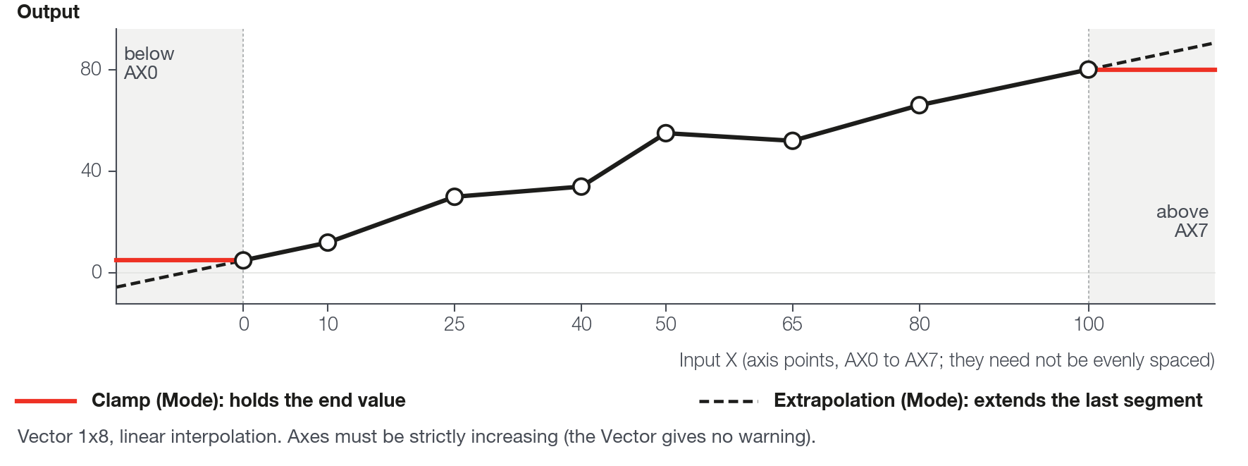
The same idea as the table, with a single axis: returns the value interpolated in a straight line between two points.
| Item | Description |
|---|---|
| Inputs | X: value on the axis. Unconnected, it is 0. |
| Output | The interpolated value. |
| Mode | Same as the table: Clamp holds the end value; Extrapolation continues the line of the end segment. |
| Axis and data | From −100000 to 100000. A new vector comes with axis 0, 1, 2... and data 0. |
The same rules apply for a strictly increasing axis and for an unconnected input. The vector screen does not show the out-of-order axis warning that the table screen shows: check the order yourself.
Memory: 4 bytes of working memory (map limit of 512) and 40 to 136 bytes of configuration (limit of 2048), depending on the size.
#Sizes and configuration cost
| Block | Axis points and cells | Configuration | Share of the 2048 B |
|---|---|---|---|
| Table 4x4 | 4 + 4 points, 16 cells | 106 B | 5.2% |
| Table 8x8 | 8 + 8 points, 64 cells | 330 B | 16.1% |
| Table 12x12 | 12 + 12 points, 144 cells | 682 B | 33.3% |
| Vector 1x4 | 4 points | 40 B | 2.0% |
| Vector 1x8 | 8 points | 72 B | 3.5% |
| Vector 1x12 | 12 points | 104 B | 5.1% |
| Vector 1x16 | 16 points | 136 B | 6.6% |