5. Input, math and logic blocks
#How to read the block sheets
Each block has a sheet with the same lines, in the same order. This chapter covers 11 blocks: those that bring a number into the function, those that do calculations, those that choose, those that limit and those that keep the previous result.
In the new block menu (right-click the graph, the drawing of the function), the blocks are in four categories: Inputs, Outputs, Tables and Logics. Fixed value and VCU value are in Inputs. The other nine blocks in this chapter are in Logics. This guide divides the Logics into groups (math and logic, selection, limits and state) only to make reading easier: the menu has no such groups. When you hover over a block in the menu, the right-hand column shows its help text. When the help text on the screen describes the block differently, this guide's description prevails.
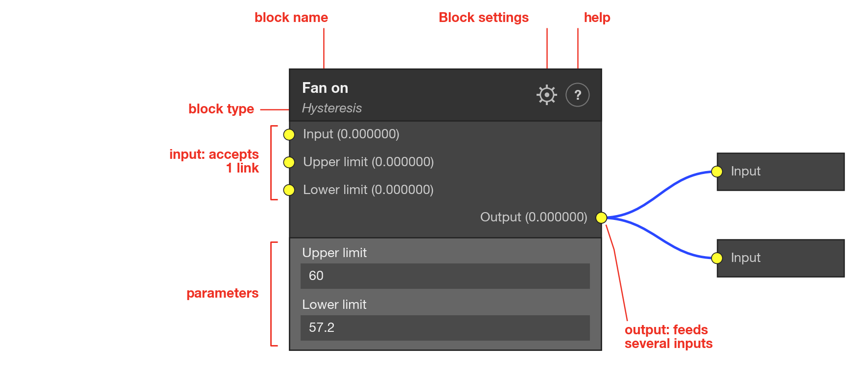
A block has a title (the name you gave it and, in smaller letters, the type), input sockets on the left, output sockets on the right, and parameters in the body. A socket is the point where a link connects. Next to each socket, the screen shows the name and the current value, with 6 decimal places, calculated by FuelTech Vision on the computer. The gear in the title opens Block settings.
| Sheet line | What it shows |
|---|---|
| Inputs | The input sockets, with the name the screen shows, and what each one receives. It says what the value is if the socket has no link. |
| Output | What the block delivers at the output socket. |
| Name of a parameter | A field in the body of the block, with the range, the default and the unit. The parameters of the blocks in this chapter can be shown on the User screen. |
| Text below the table | The exact rule of the block, in plain language. The highlight boxes carry the main pitfall. |
| Memory | How much the block takes from the VCU's two memories (explained below). |
Unconnected input is an input socket with no link. It is 0, not the last value it had. The editor does not warn when an input has no link. There are exceptions, described in the sheets: the Min and Max sockets of the Limiter and the Upper limit and Lower limit sockets of the Hysteresis use the block parameter instead, and the Set value of the SR Latch is 1.
Every link carries a decimal number. A logic signal is the number 1 (true) or 0 (false). What counts as true depends on the block. In the Logic block, an input is true when it is greater than 0: 0, negative numbers and an unconnected input are false, and 0.3 is already true. In the SR Latch, Set and Reset become active when they exceed the block's own Threshold (default 0.5).
The end of each sheet says how much the block takes from two VCU memories, shared among all the enabled functions in the map. The working memory (limit of 512 bytes) stores what the block calculates in each cycle: the output and, in some blocks, a state. The configuration memory (limit of 2048 bytes) stores the block type, the connections and the parameters. The editor's memory meter shows both, in the RAM and Settings bars. Blocks with state (Hysteresis, SR Latch and Band multiplexer) restart from zero every time a map is written to the VCU.
#Inputs
#Fixed value
Always delivers the same number, which you type in the block.
| Item | Description |
|---|---|
| Inputs | None. |
| Output | Value: the number typed. |
| Fixed value | Free text, with up to 6 decimal places. Range from −999999 to 999999 (the screen does not block values outside it). Default 0. No unit. |
The output is the number typed, on every execution of the function. The number has about 7 significant digits. Each constant takes memory, and one output can feed several inputs: reuse the same Fixed value instead of repeating the constant.
Memory: 4 bytes of working memory (map limit of 512) and 6 bytes of configuration (limit of 2048).
#VCU value
Reads a channel that the VCU maintains (a sensor reading, a calculated value, a state, data coming from CAN or written by a Value for VCU block) and delivers the number on the link.
| Item | Description |
|---|---|
| Inputs | None. |
| Output | Value: the number the VCU holds, at this instant, in the chosen channel. |
| VCU data | List with search, in alphabetical order. Default None. The channels that have a source in the map appear marked. |
The flag channels (on or off) only deliver 0 or 1. If the list ends in an item with no name or called Math channel, do not choose it: it is not a VCU channel and reads 0.
Eight channels appear in the list, but the custom function cannot read them: the value is always 0. They are Processor temperature, VCU Time, VCU Date, VCU Time (the second channel has the same name), Odometer, Trip odometer, Hourmeter and Trip hourmeter. On the FT470, the inputs Analog input #28: Voltage to Analog input #36: Voltage also always read 0.
Unit: the block delivers the number as the VCU stores it, without scale conversion. The FuelTech Vision measurement table declares a base unit per channel, for example MAP (the intake manifold pressure) in bar, temperature in °C and speed in km/h. Check the unit of the channel before comparing the value with a constant: the value stays in the base unit even when the screen shows °F, psi or mph, and the examples in this guide use the base units.
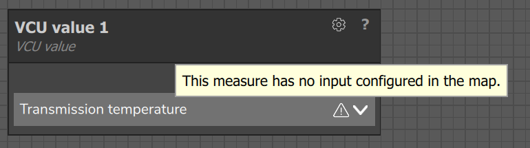
When the measurement comes from a physical input and nothing feeds it, the block shows a warning icon with the text This measure has no input configured in the map. The warning only exists for measurements that come from an input: calculated channels do not generate it.
Memory: 4 bytes of working memory (map limit of 512) and 4 bytes of configuration (limit of 2048).
#Math and logic
#Math operation
Does a calculation with two numbers and delivers the result.
| Item | Description |
|---|---|
| Inputs | Data 1 and Data 2: the two numbers. With no link, they are 0. |
| Output | Output: the result of the calculation. |
| Operation | List, default Add. The six options are in the table below. |
| Operation | Output |
|---|---|
| Add | Data 1 + Data 2 |
| Subtract | Data 1 − Data 2 |
| Multiply | Data 1 × Data 2 |
| Divide | Data 1 ÷ Data 2. If Data 2 is 0, the output is 0. |
| Minimum | The smaller of the two (if they are equal, that value). |
| Maximum | The larger of the two (if they are equal, that value). |
Memory: 4 bytes of working memory (map limit of 512) and 7 bytes of configuration (limit of 2048).
#Logic
Does a logic operation between two inputs and delivers 1 or 0.
| Item | Description |
|---|---|
| Inputs | A and B: the two operands. With no link, they are 0 (false). NOT ignores B. |
| Output | Output: 1 (true) or 0 (false). The block does not pass on the value of the input. |
| Operator | List, default AND. The names are not translated: the screen shows them in English in every language. The six options are in the table below. |
| Operator | The output is 1 when |
|---|---|
| AND | A and B are true. |
| OR | A or B (or both) is true. |
| NOT | A is false. B is not used. |
| XOR | Only one of the two is true. |
| NAND | The two are not true at the same time (the inverse of AND). |
| NOR | Neither of the two is true (the inverse of OR). |
Memory: 4 bytes of working memory (map limit of 512) and 7 bytes of configuration (limit of 2048).
#Selection
#Switch
Compares a reference with one or two limits and delivers one of two values.
| Item | Description |
|---|---|
| Inputs | Reference: the number compared. True data and False data: the two possible values. Upper limit and Lower limit: the limits. With no link, all are 0, including the limits. |
| Output | Output: the value of True data or of False data, not a 0 or 1. |
| Mode | List, default Above. It sets the condition, in the table below. |
| Mode | True condition |
|---|---|
| Above | Reference > Upper limit. Only the Upper limit counts. |
| Below | Reference < Lower limit. Only the Lower limit counts. |
| In the range | Reference > Lower limit and Reference < Upper limit. |
| Out of range | Reference < Lower limit or Reference > Upper limit. |
If the condition is true, the output is the True data; otherwise, it is the False data. The comparisons are strict: at the exact value of the limit the condition is false. There is no hysteresis; for that, use the Hysteresis block. On the screen, the limit socket that the mode does not use is disabled.
Memory: 4 bytes of working memory (map limit of 512) and 13 bytes of configuration (limit of 2048).
#Multiplexer
Chooses one of four input channels by the selector number.
| Item | Description |
|---|---|
| Inputs | Selector: the number that chooses. Channel 1 to Channel 4: the possible values. With no link, all are 0. |
| Output | Output: the value of the chosen channel. If the chosen channel has no link, the output is 0. |
The selector is truncated to an integer: the decimal part is discarded. From 0 to 0.99 it chooses Channel 1; from 1 to 1.99, Channel 2; from 2 to 2.99, Channel 3; from 3 upward, Channel 4. Outside that range there is no error: negative values choose Channel 1. A selector with no link (0) also chooses Channel 1. The block has no parameters and no state.
Memory: 4 bytes of working memory (map limit of 512) and 12 bytes of configuration (limit of 2048).
#Band multiplexer
Chooses one of four channels according to the range of values in which the selector falls.
| Item | Description |
|---|---|
| Inputs | Selector: the number tested. Channel A to Channel D: the possible values. With no link, all are 0. |
| Output | Output: the value of the channel of the range that matched. |
| Channel A to Channel D (Min and Max) | The ends of the range of each channel, from −999999 to 999999. Defaults: A from 0 to 1, B from 1 to 2, C from 2 to 3 and D from 3 to 4. |
| No match | What comes out when no range matches: Output = 0 (default) or Follow last valid. |
The block tests the ranges in the order A, B, C, D and stops at the first one that contains the selector (the ends count: Min ≤ selector ≤ Max). The output is the value of the channel of that range, which the block memorizes as the last valid value. If no range matches, the output is 0 or the memorized value, according to No match. The memorized value starts at 0 and is what the channel was worth when the range matched: if the channel changes later, the output does not follow. A range with Min greater than Max is off.
Memory: 8 bytes of working memory (map limit of 512) and 48 bytes of configuration (limit of 2048).
#Limits
#Limiter
Keeps a number between a minimum and a maximum.
| Item | Description |
|---|---|
| Inputs | Input: the number to limit (with no link, it is 0). Min and Max: if they have a link, they replace the parameters. |
| Output | Output: the input, already limited. |
| Minimum Value | From −999999 to 999999. Default 0. It applies when the Min socket has no link. |
| Maximum Value | From −999999 to 999999. Default 100. It applies when the Max socket has no link. |
If the input is smaller than the minimum, the minimum comes out. Then, if the result is greater than the maximum, the maximum comes out. Having a link is what counts, not the value: a Min connected to a source that is 0 limits at 0, and the parameter is ignored.
Memory: 4 bytes of working memory (map limit of 512) and 16 bytes of configuration (limit of 2048).
#Deadband
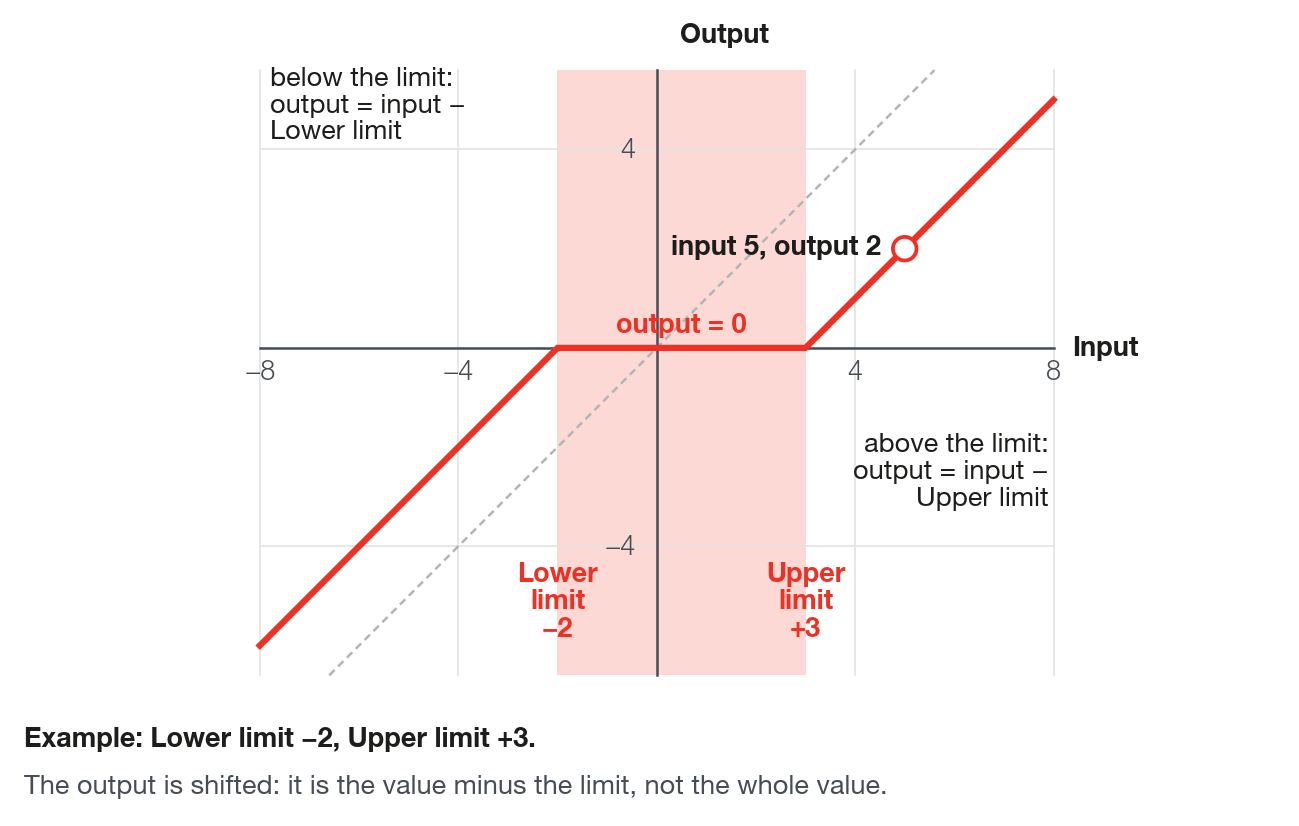
Zeroes the signal while it is inside a range. Outside it, delivers only the part beyond the limit.
| Item | Description |
|---|---|
| Inputs | Input. With no link, it is 0 and goes into the calculation (with the range from 5 to 10, the output would be −5). There are no sockets for the limits: they come only from the parameters. |
| Output | Output: 0 inside the range; outside it, the input minus the limit exceeded. |
| Lower limit | From −999999 to 999999. Default −1. |
| Upper limit | From −999999 to 999999. Default +1. |
input above the upper limit:   output = input − upper limit
input below the lower limit:   output = input − lower limit
input inside the range (includes the limits):  output = 0
With the default range, from −1 to 1: input 3 gives output 2, input −4 gives output −3 and input 0.7 gives output 0.
Memory: 4 bytes of working memory (map limit of 512) and 12 bytes of configuration (limit of 2048).
#State
#Hysteresis
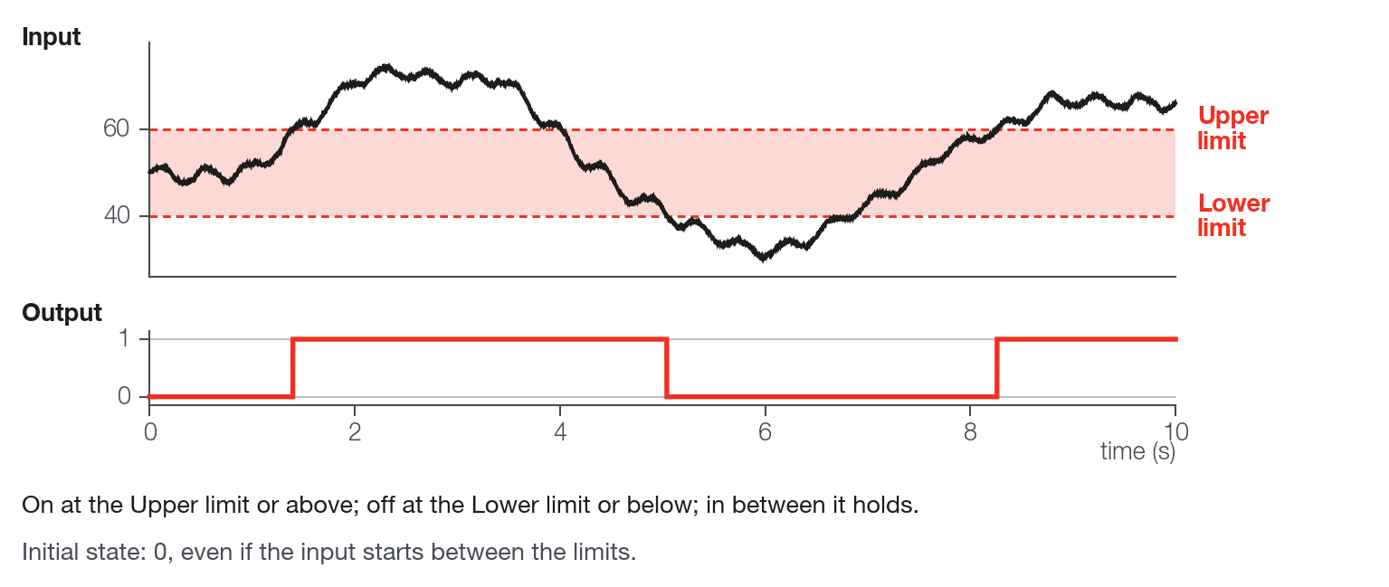
Turns an output on when the signal rises to a limit and turns it off only when it falls to a lower limit.
| Item | Description |
|---|---|
| Inputs | Input: the signal (with no link, it is 0). Upper limit and Lower limit (the sockets): if they have a link, they replace the parameters. |
| Output | Output: 1 or 0. |
| Upper limit | From −999999 to 999999. Default 100. |
| Lower limit | From −999999 to 999999. Default 0. |
Input greater than or equal to the upper limit: the output goes to 1. Input smaller than or equal to the lower limit: the output goes to 0. Between the two, the output keeps the previous value. At the exact limits the output also changes.
Memory: 8 bytes of working memory (map limit of 512) and 16 bytes of configuration (limit of 2048).
#SR Latch
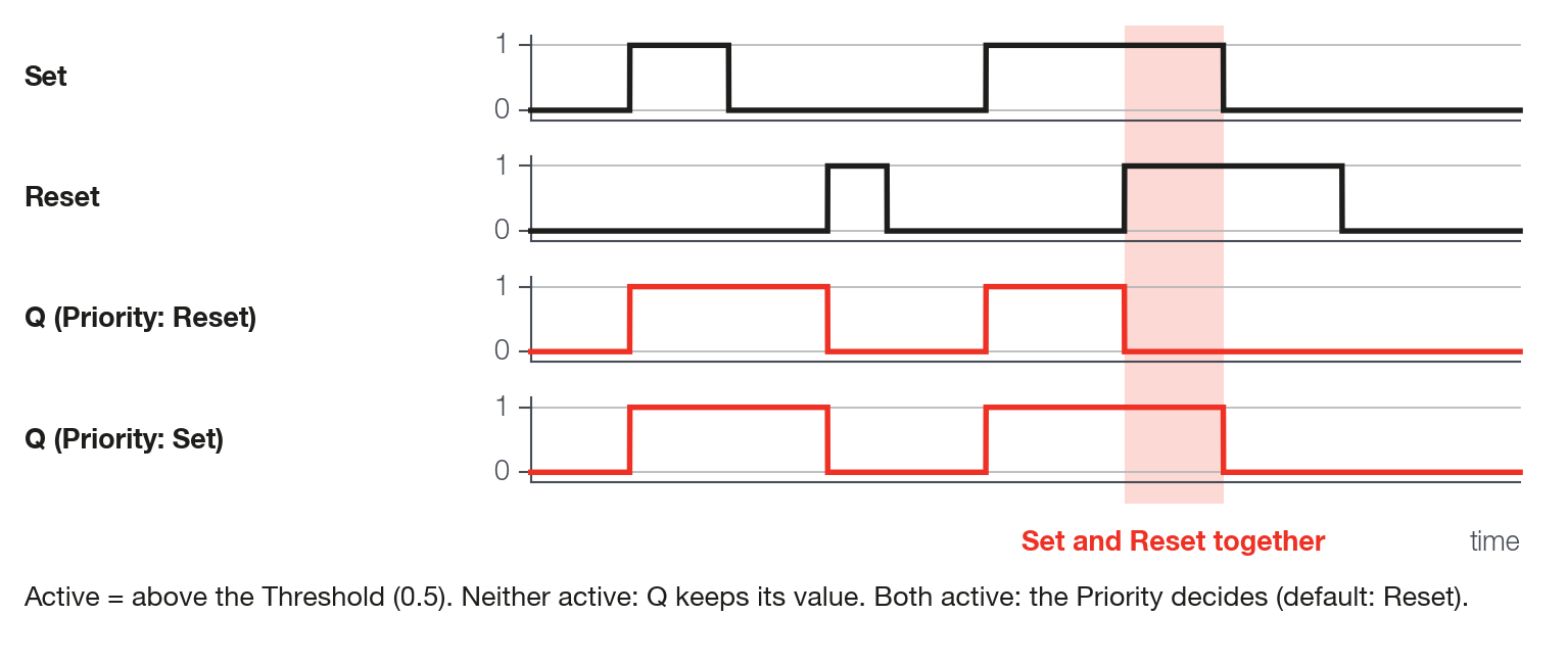
Stores a value: a pulse on Set writes it, a pulse on Reset zeroes it, and the value stays stored between the pulses.
| Item | Description |
|---|---|
| Inputs | Set and Reset: become active when they exceed the Threshold. With no link, they are 0 and are never active. Set value: the value to store; with no link, it is 1. |
| Output | Q: the stored value. Q bar: the second output, which the screen writes as a Q with a bar over it. |
| Threshold | From 0 to 10000 (the screen does not accept negative values). Default 0.5. The same threshold applies to Set and Reset. An input at 0 is never active, because 0 is not greater than 0. |
| Priority | List: Reset (default) or Set. It decides which one wins when both are active at the same time. |
- Only Set active: Q = Set value. While Set stays active, Q follows the Set value; when Set drops, Q freezes at the last value.
- Only Reset active: Q = 0.
- Both active: with Reset priority, Q = 0; with Set priority, Q = Set value.
- Neither active: Q keeps the previous value.
Q bar is the Set value when Q is 0 and is 0 when Q is different from 0: only with the Set value at 1 is it the inverse of Q, and with the Set value at 0 both are 0. Q starts at 0 when the VCU is powered on and at every map write; on the first execution, Q bar becomes the Set value. To store a signal of 0 and 1, leave the Set value without a link: it is 1.
Memory: 8 bytes of working memory (map limit of 512) and 16 bytes of configuration (limit of 2048).