9. Examples
The seven examples, in increasing order of size, are models to study and starting points: adjust the values to your vehicle, test with the engine off (step 9) and confirm in the log (step 10) before using one in a car. Each example is independent of the others. Added together, they exceed the map's memory limit and use the same log channels: install one at a time or renumber the Custom measurement entries.
| Example | Blocks | Working (of 512 B) | Configuration (of 2048 B) |
|---|---|---|---|
| Fan on/off by temperature | 5 | 20 B | 38 B |
| Output by RPM and TPS | 10 | 44 B | 71 B |
| Acceleration enrichment by derivative | 17 | 100 B | 350 B |
| Solenoid current control | 30 | 144 B | 237 B |
| Timed single pulse | 38 | 212 B | 324 B |
| Deceleration fuel cut | 46 | 292 B | 478 B |
| Idle by torque reserve | 62 | 312 B | 902 B |
In the tables, the blocks appear in signal order and with the type name, as in the menu. In your map, use the names you gave in step 7. Examples 3 to 7 change the fuel injection and command a solenoid, an actuator, a fuel cut and the throttle: read the warning of each before testing.
The User screen line of each example says what to expose to the end customer, following the policy in the User screen chapter: channels, outputs and the VCU action limits stay hidden.
#Fan on/off by temperature
Turns a fan on when the temperature goes above one limit and only turns it off when it falls below another, lower one, so that it does not keep turning on and off right at the limit.

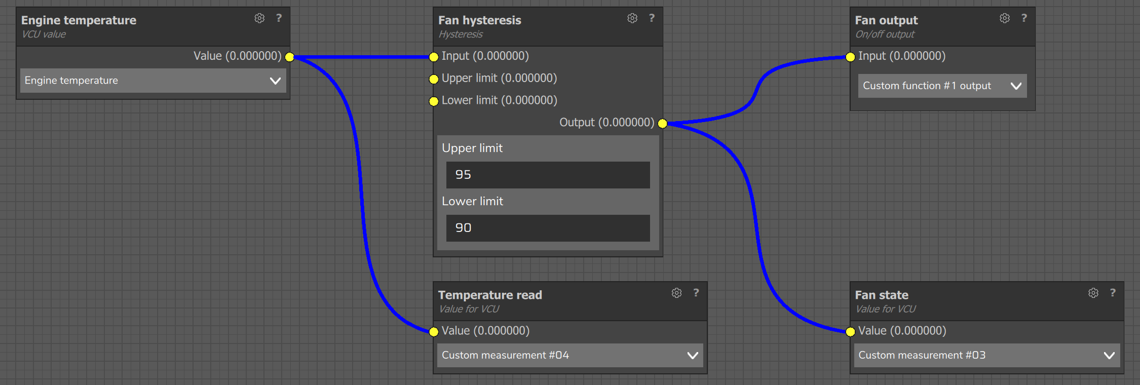
| Block on screen | Role in the example | Main value or setting |
|---|---|---|
| VCU value | Reads the temperature | VCU data: Engine temperature |
| Hysteresis | Turns on above the upper limit and off below the lower limit | Upper limit 95 °C and lower limit 90 °C (example values) |
| On/off output | Drives the fan | Output: Custom function #1 output |
| Value for VCU (2) | Records the state and the temperature read | Custom measurement #03 and #04 |
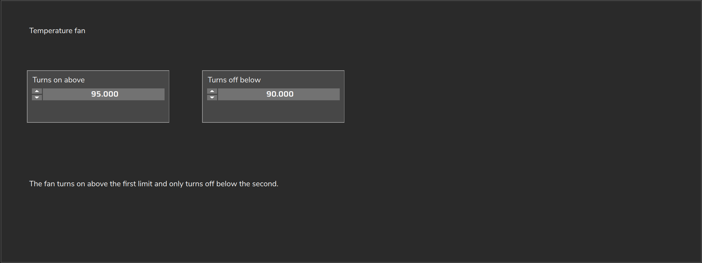
- User screen: expose the two Hysteresis limits, with the names "Turns on above" and "Turns off below".
- Log: Custom measurement #03 = state (1 on, 0 off). Custom measurement #04 = temperature as the function reads it.
- Customize: (1) The temperature channel in VCU data. (2) The limits: check in Custom measurement #04 that the temperature arrives in degrees Celsius. (3) Assign Custom function #1 output to a pin on the Outputs screen, where it appears with the same name. Check the VCU installation manual for the type and current of the chosen output. (4) The Hysteresis starts off when the map loads: if the temperature is already between the limits, the fan only turns on when it goes above the upper limit.
#Output by RPM and TPS
Drives an output only when the engine speed goes above a value and the throttle goes above an opening. It serves as a base for any output that depends on two conditions.
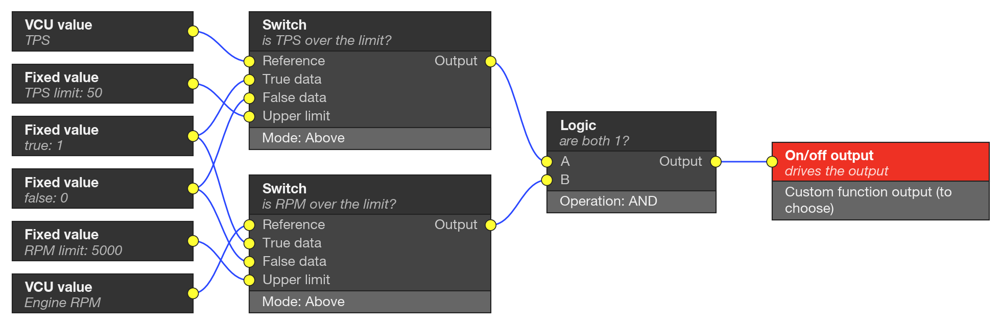
| Block on screen | Role in the example | Main value or setting |
|---|---|---|
| VCU value (2) | Reads opening and engine speed | TPS and Engine RPM |
| Fixed value (4) | True result, false result and the two limits | 1; 0; 50; 5000 |
| Switch (TPS) | Is 1 if the TPS goes above the limit | Mode Above; upper limit 50 |
| Switch (RPM) | Is 1 if the engine speed goes above the limit | Mode Above; upper limit 5000 |
| Logic | Is 1 only if both Switch blocks are 1 | Operation AND |
| On/off output | Drives the output | Custom function output of your choice |
- User screen: the example has no screen. For the customer to adjust it, expose the Fixed value field of the two limits, with a custom name.
- Log: the example records nothing. To see the condition, connect the Logic output to a Value for VCU (Custom measurement #03): this adds 6 bytes of configuration.
- Customize: (1) The limits 50 and 5000. (2) The output function, which must be assigned to a pin on the Outputs screen. (3) Both Switch blocks compare strictly and with no hysteresis: with the value sitting right on the limit the output can oscillate. Replace the Switch with a Hysteresis, as in the previous example, if that happens.
#Acceleration enrichment by derivative
Injects extra fuel on a quick pedal press (tip-in), proportional to the speed at which the throttle opens, with a smooth decay and scaled by load and by engine temperature.
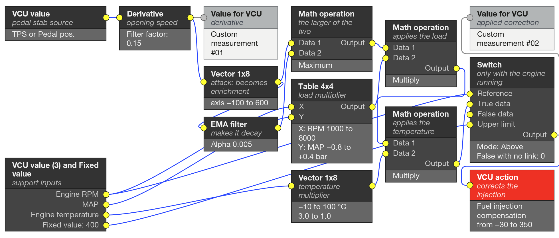
| Block on screen | Role in the example | Main value or setting |
|---|---|---|
| VCU value | Tip-in source | TPS (default) or Pedal pos. |
| Derivative | Opening speed, in % per second | Filter factor 0.15 |
| Vector 1x8 (attack) | Turns the derivative into enrichment (%) | Axis −100 to 600; values −20 to 120 |
| EMA filter | Makes the enrichment decay | Alpha 0.005 |
| Math operation | Maximum of the attack and the decay | Operation Maximum |
| Table 4x4 (load) | Multiplier by RPM and MAP | RPM 1000 to 8000; MAP −0.8 to +0.4 bar; cells 0 to 1.2 |
| Math operation | Applies the load | Multiply |
| Vector 1x8 (temperature) | Multiplier by engine temperature | −10 to 100 °C; 3.0 to 1.0 |
| Math operation | Applies the temperature | Multiply |
| Fixed value, Switch | Only lets it through with the engine running | Mode Above; 400 rpm |
| VCU action | Fuel injection compensation, in % | Minimum −30; maximum 350 |
| Value for VCU (2) | Records the derivative and the correction applied | Custom measurement #01 and #02 |
- User screen: 3 fields and 3 tables. Fields: the Filter factor of the Derivative, the Alpha of the EMA filter and the minimum RPM of the Switch. Tables: the attack vector, the load table and the temperature vector, whole.
- Log: Custom measurement #01 = derivative. Custom measurement #02 = correction applied.
- Customize: (1) The source in VCU data: TPS or Pedal pos. (2) The axis of the attack Vector 1x8: record Custom measurement #01 during tip-ins and adjust the axis to the real range. If the input only updates from time to time, the derivative comes out in spikes: filter the input before the Derivative. (3) The MAP axis goes up to +0.4 bar and the +0.4 row is zeroed: in Clamp mode, above the last point the table repeats that row and does not enrich from +0.4 bar upward.
#Solenoid current control
Keeps the current of a proportional coil at the value requested by a 0 to 100% command, through a PWM output, with feedback from the measured current.
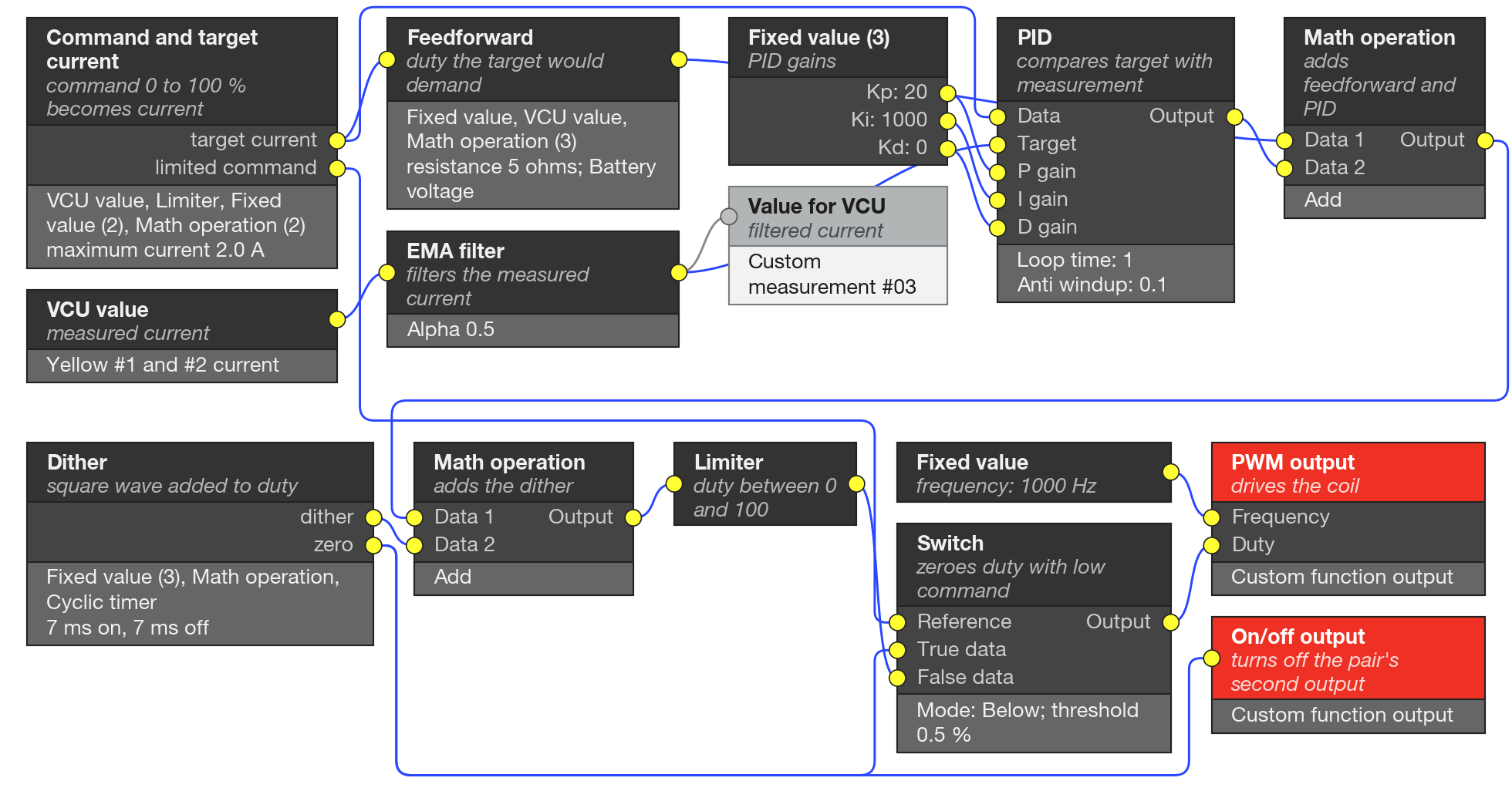
| Block on screen | Role in the example | Main value or setting |
|---|---|---|
| VCU value, Limiter, Fixed value (2), Math operation (2) | Command from 0 to 100% becomes target current | Target = command ÷ 100 × maximum current; maximum current 2.0 A |
| VCU value | Reads the measured current | Yellow #1 and 2# current (written this way on the screen), in A |
| EMA filter | Filters the measured current | Alpha 0.5 |
| Fixed value (3) | Proportional (Kp), integral (Ki) and derivative (Kd) gains of the PID | 20; 1000; 0 |
| PID | Compares the target with the measurement and corrects | Loop time 1; anti windup 0.1 |
| Fixed value, VCU value, Math operation (3) | Feedforward: duty the target would demand by itself | Target × resistance ÷ Battery voltage × 100; resistance 5 ohms |
| Math operation | Adds the feedforward and the PID correction | Add |
| Fixed value (2), Math operation, Cyclic timer | Dither: adds to the duty a square wave of +5 and −5 | Amplitude 5%; 7 ms on and 7 ms off |
| Math operation | Adds the dither to the duty | Add |
| Limiter | Keeps the duty between 0 and 100% | 0 to 100 |
| Switch | Zeroes the duty if the command falls below the threshold | Mode Below; threshold 0.5% |
| PWM output | Drives the coil | Frequency 1000 Hz, from a Fixed value |
| On/off output | Keeps the pair's second output off | Input 0 |
| Value for VCU | Records the filtered current | Custom measurement #03 |
- User screen: 13 fields: maximum current, filter, Kp, Ki, Kd, loop time, anti windup, resistance, dither amplitude and times, cutoff threshold and PWM frequency. The gains are inputs of the PID, not fields: that is why each one comes from a Fixed value.
- Log: Custom measurement #03 = filtered current.
- Customize: (1) The command channel: use one that only you write to, such as a Custom measurement of another function. A channel with an owner (physical input or CAN) can have its value overwritten. (2) The pair of yellow outputs: assign both Custom function output functions on the Outputs screen and use the current channel of the same pair. (3) The coil's resistance and maximum current, and check in Custom measurement #03 that the measured current and the target are in the same unit. (4) The gains: tune them from the log. (5) The Cyclic timer works in whole milliseconds: a fractional value counts as the next integer (7.14 becomes 8 ms), which is why the example uses 7 ms, close to 71 Hz. The EMA filter with Alpha 0.5 filters little.
#Timed single pulse
Turns an output on only once per launch, for a fixed time, after a valid launch, triggered by a quick lift off the throttle pedal or by a button. It only re-arms when the launch stops being valid.
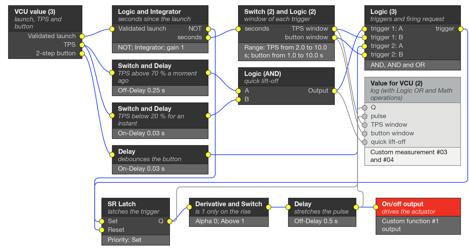
| Block on screen | Role in the example | Main value or setting |
|---|---|---|
| VCU value (3) | Reads the launch, the TPS and the button | Validated launch, TPS, 2-step button |
| Logic (NOT), Integrator | Counts the seconds since the valid launch and resets when it stops being valid | Gain 1; reset by the invalid launch |
| Switch (2), Logic (2, AND) | Window of each trigger, combined with its on/off | TPS from 2.0 to 10.0 s; button from 1.0 to 10.0 s |
| Switch (Above), Delay (Off-Delay) | TPS went above 70% a moment ago | 70%; 0.25 s |
| Switch (Below), Delay (On-Delay) | TPS below 20% for a short time, to discard an isolated reading | 20%; 0.03 s |
| Logic (AND) | Quick lift-off: was above 70% and is below 20% | |
| Delay (On-Delay) | Debounces the button | 0.03 s |
| Logic (3: AND, AND and OR) | Trigger 1, trigger 2 and firing request (one or the other) | |
| SR Latch | Latches the trigger and only releases with the invalid launch | Priority Set; threshold 0.5 |
| Derivative, Switch (Above) | Edge detector: is 1 only in the run in which the latch rises | Filter factor 0; limit 1 |
| Delay (Off-Delay) | Stretches the pulse | 0.5 s |
| On/off output | Drives the actuator | Custom function #1 output |
| Logic (OR), Math operation (3), Value for VCU (2) | State code and quick lift-off, in the log | Custom measurement #03 and #04 |
- User screen: 9 fields: TPS opens above 70%, TPS closes below 20%, maximum closing time 0.25 s, TPS arms after 2.0 s, button arms after 1.0 s, window ends at 10.0 s, TPS trigger on or off, button trigger on or off, and pulse duration 0.5 s.
- Log: Custom measurement #03 = state (0 disarmed, 1 armed, 2 triggered, 3 output on). Custom measurement #04 = quick lift-off seen.
- Customize: (1) The output function, assigned to a pin on the Outputs screen. (2) The thresholds: Custom measurement #04 is 1 whenever the quick lift-off is seen, inside or outside the window: use it in a dry test. (3) The example depends on the Validated launch and 2-step button channels: check in the log that both change as you expect. (4) All times are in seconds, which is what the Delay time (s) field of the Delay requires.
#Deceleration fuel cut
Cuts the injection (deceleration fuel cut-off, DFCO) when the driver lifts off the pedal at high RPM and with engine-braking vacuum. The cut comes in as a ramp and the return is smoothed by ignition and by a short enrichment.
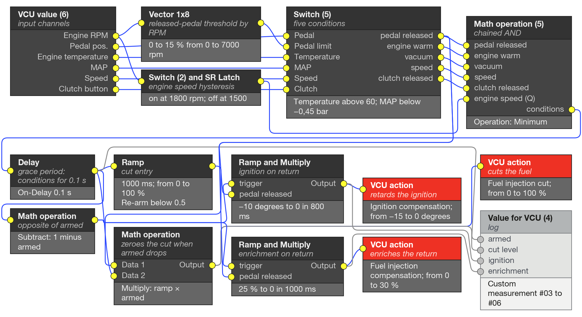
| Block on screen | Role in the example | Main value or setting |
|---|---|---|
| VCU value (6) | Reads engine speed, pedal, temperature, MAP, speed and clutch | Engine RPM, Pedal pos., Engine temperature, MAP, Speed, Clutch button |
| Vector 1x8 | Released-pedal threshold, by RPM | 0 to 15% from 0 to 7000 rpm; 2% at 1000 and 2000 rpm |
| Switch (5) | Pedal released, engine warm, vacuum, speed and clutch released | Temperature above 60 °C; MAP below −0.45 bar; speed above −1 (disabled); button below 0.5 |
| Switch (2), SR Latch | Engine speed hysteresis: allows the cut above one engine speed and releases below another | 1800 rpm and 1500 rpm; Priority Reset |
| Math operation (5, Minimum) | Chained AND: is 1 only if the six conditions are 1 | |
| Delay (On-Delay) | Grace period: only arms the cut if the conditions hold for 0.1 s in a row | 0.1 s; if the condition drops earlier, the count is canceled |
| Ramp | Cut entry: rises from 0 to 100% | 1000 ms; Rearm below: 0.5 |
| Math operation (Multiply) | Zeroes the cut as soon as the armed signal drops | Ramp output × armed |
| VCU action | Fuel injection cut, level from 0 to 100% | Minimum 0; maximum 100 |
| Math operation | Opposite of the armed signal | Subtract: 1 minus armed |
| Ramp, Math operation | Ignition on return, only with the pedal released | −10 degrees returning to 0 in 800 ms |
| VCU action | Ignition compensation | Minimum −15; maximum 0 degrees |
| Ramp, Math operation | Enrichment on return, only with the pedal released | 25% returning to 0 in 1000 ms |
| VCU action | Fuel injection compensation | Minimum 0; maximum 30% |
| Value for VCU (4) | Records the cut and the compensations | Custom measurement #03 to #06 |
- User screen: 11 fields and the pedal threshold vector. Fields: minimum temperature, vacuum ceiling, cut RPM, fuel resume RPM, minimum speed (−1 turns it off), grace period, entry ramp, ignition retard and ramp on return, enrichment and decay on return.
- Log: Custom measurement #03 = cut armed (0 or 1). #04 = cut level applied, after the multiplication (%). #05 = ignition compensation (degrees). #06 = enrichment (%). With the cut armed, #05 and #06 are already at −10 degrees and 25%, including during the cut's entry ramp: the return ramps wait, held at the initial value.
- Customize: (1) The vacuum ceiling: measure it in the log (idle should stay above the ceiling and engine braking below it). (2) The cut and fuel resume RPM. (3) The pedal threshold is a vector by RPM (Vector 1x8), not a fixed value: adjust the points to the car's pedal. (4) Without a clutch button the channel stays at 0 and the condition is always 1: confirm in the log. (5) The cut competes with the native cuts by the highest level, and the compensation adds to the native corrections: check that no native cut or acceleration fuel enrichment function does the same job.
#Idle by torque reserve
Holds idle at the RPM target with two actuators: the ignition, which is fast and works with a few degrees of reserve, and the air from the electronic throttle, which is slow. It is the most complete example: it serves as a case study, and the table shows the drawing in groups of blocks.
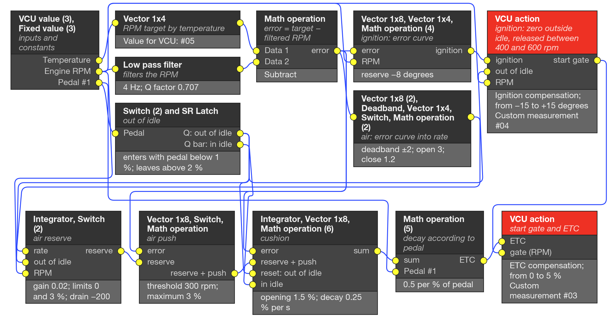
| Block on screen | Role in the example | Main value or setting |
|---|---|---|
| VCU value (3), Fixed value (3) | Inputs and constants 0, 1 and 0.5 | Engine temperature, Engine RPM, Pedal #1 |
| Vector 1x4, Value for VCU | RPM target by temperature, recorded | 1110, 985, 960, 960 rpm at 20, 50, 70, 90 °C; #05 |
| Low pass filter | Filters the RPM | Frequency 4 Hz; Q factor 0.707 |
| Math operation | Error = target − filtered RPM | Subtract |
| Vector 1x8, Math operation (4), Vector 1x4 | Ignition: error curve in degrees, separation of advance and retard, retard that fades out at high RPM | Reserve −8 degrees; maximum retard −15; maximum advance +2; full retard up to 1300 and zero above 1800 rpm |
| Switch (2), SR Latch, Fixed value (2) | "Out of idle": enters idle with the pedal below 1% and leaves with the pedal above 2% | Priority Set |
| Switch, Vector 1x4, Math operation, VCU action, Value for VCU | Zeroes the ignition outside idle, releases between 400 and 600 rpm and applies the Ignition compensation | Minimum −15; maximum +15 degrees; #04 |
| Vector 1x8, Deadband, Vector 1x4, Switch, Math operation (2), Fixed value (2) | Air: error curve into rate, deadband and asymmetric gain | Deadband ±2; open 3; close 1.2 |
| Integrator, Switch (2), Fixed value (2) | Air reserve: integrates the rate, freezes outside idle and drains with the engine stopped | Gain 0.02; limits 0 and 3%; minimum RPM 400; drain −200 |
| Vector 1x8, Switch, Fixed value, Math operation | Air push when the RPM error is large | Threshold 300 rpm; maximum 3% |
| Integrator, Vector 1x8, Fixed value (2), Math operation (6) | Cushion: extra initial opening used up slowly near the target, only at idle | Opening 1.5%; decay 0.25% per second |
| Math operation (5), Fixed value | Air decay as the pedal goes above 1% | 0.5 per % of pedal |
| Math operation, VCU action, Value for VCU | Start gate and ETC compensation | Minimum 0; maximum 5%; #03 |
- User screen: the fields for deadband and air gains, air reserve gain and limits, idle entry and exit by pedal, minimum RPM and drain, push threshold, decay by pedal and cushion, and 7 text boxes. In FuelTech Vision 3.0, a vector goes to the screen as a whole, through the block's Show table in User screen checkbox: check it on the vectors the customer needs to adjust (temperature target, ignition reserve, gates and curves).
- Log: Custom measurement #03 = ETC compensation (%). #04 = ignition compensation (degrees). #05 = RPM target.
- Customize: (1) It only works on a car with an electronic throttle: the action list has no action for an idle air valve. (2) The native idle control comes after the ignition compensation and can replace the total: in the idle control menu, turn off only the ignition timing control toggle, keep the native control on for the air base and copy the target from the native table to this function's target. The two targets must be the same number. (3) First test: with the ignition on and the engine off, Custom measurement #03 and #04 should read 0.000, because the start gate zeroes both below 400 rpm.