8. From problem to graph
A good custom function starts on paper, not in the editor. This chapter is the 11-step roadmap that the examples in the next chapter follow. The complete drawing of the function, with all its blocks and links, is the graph.
#Step 1: write the goal in one sentence
Write what the function does and when it acts, for example: "turns the fan on above 95 °C and off below 90 °C". Each block uses up memory of the whole map: there are 512 bytes of working memory and 2048 bytes of configuration for the 10 functions combined, and only enabled functions count. A short goal avoids blocks that serve no purpose.
#Step 2: list the inputs
- Each input is a VCU value block. It reads the channel you choose in the list, at the value the VCU stores, without converting to the unit the screen shows. Check the unit by reading the channel in the log.
- The block does not check whether the channel is valid: with the sensor disconnected it delivers whatever is stored in the channel. An input with no link reads 0.
- Some channels in the list always read 0, among them Processor temperature, Odometer, Hourmeter and the VCU date and time. The complete list is in the chapter Input, math and logic blocks.
- The editor shows an alert on the block when the channel comes from an input that is not configured in the map. See the Input, math and logic blocks chapter.
#Step 3: condition the signal
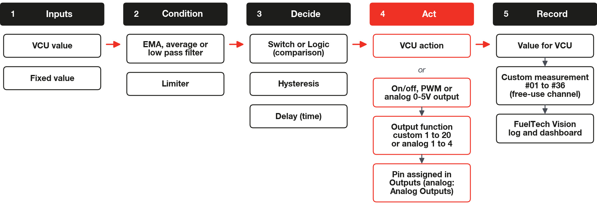
Conditioning means getting the signal ready for a decision: filtering, limiting and scaling. Filter before differentiating.
- The Derivative divides the difference between two consecutive runs by the real time between them and delivers units per second, with no window. A step on the input becomes a spike. Filter the input beforehand with an EMA filter or a Low pass filter.
- In the EMA filter, Alpha is the weight of the new sample on every execution of the function (about 1 ms, depending on the processor load): a small Alpha filters more. The time constant is −1 ms ÷ ln(1 − Alpha): Alpha 0.005 gives about 200 ms and 0.15 gives about 6 ms.
- The Limiter comes with minimum 0 and maximum 100: a Limiter left at the default cuts values that are negative or above 100. The Deadband delivers 0 inside the band and, outside it, the input minus the limit. See the Input, math and logic blocks and Time, filter, control and table blocks chapters.
#Step 4: decide
| You need to | Use | Watch out |
|---|---|---|
| Compare a value with a limit | Switch | The comparison is strict: at the exact value of the limit the condition is false. When you change the mode, move the limit link to the right socket. |
| Avoid oscillating around the limit | Hysteresis | Turns on at a value greater than or equal to the upper limit and turns off at less than or equal to the lower limit. Starts off. |
| Remember an event until a reset | SR Latch | Set and Reset count when above the threshold (0.5 by default). With both active, the Priority field decides. |
| Require the condition to last for some time | Delay (On-Delay) | Treats the input as on/off (greater than 0). The time is in seconds. It does not delay an analog signal. |
| Stay on after the condition drops | Delay (Off-Delay) | Same rules as On-Delay. |
| Combine conditions | Logic | Any value greater than 0 is true: 0.3 is already true. |
#Step 5: act
- The VCU action adds to or replaces a value inside the VCU (17 actions). Compensations add to the native corrections. Replacement actions have no adjustable priority and lose to native functions such as the launch functions (2-step, 3-step and burnout), gear shifting and boost control by ETC. The block limits the value between Minimum and Maximum, and a new block comes with both at 0: adjust the Minimum and the Maximum. Two separate cases: Ignition timing beats the hard cut, the rev limiter, but only in the fixed ignition timing, and the limiter's cut keeps acting; and the High resolution ignition cut block competes with traction control, 2-step, 3-step and burnout for the highest percentage.
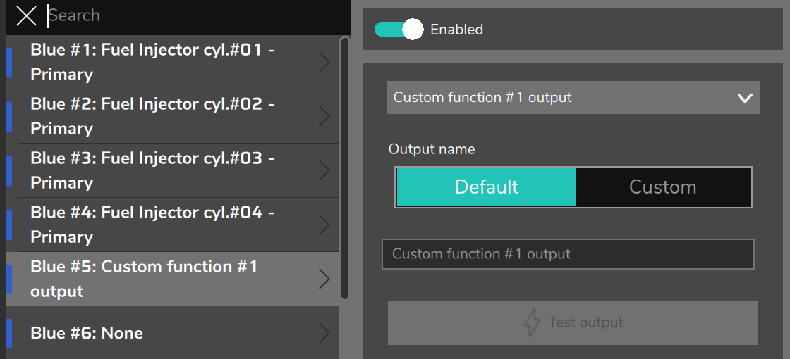
- On/off output, PWM output and Analog output 0-5V choose an output function, for example Custom function #1 output, not a pin. Assign that function to a pin on the Outputs screen (the analog output, on the Analog Outputs screen): without this the block stays silent and nothing warns you. See the Output blocks chapter.
#Step 6: record
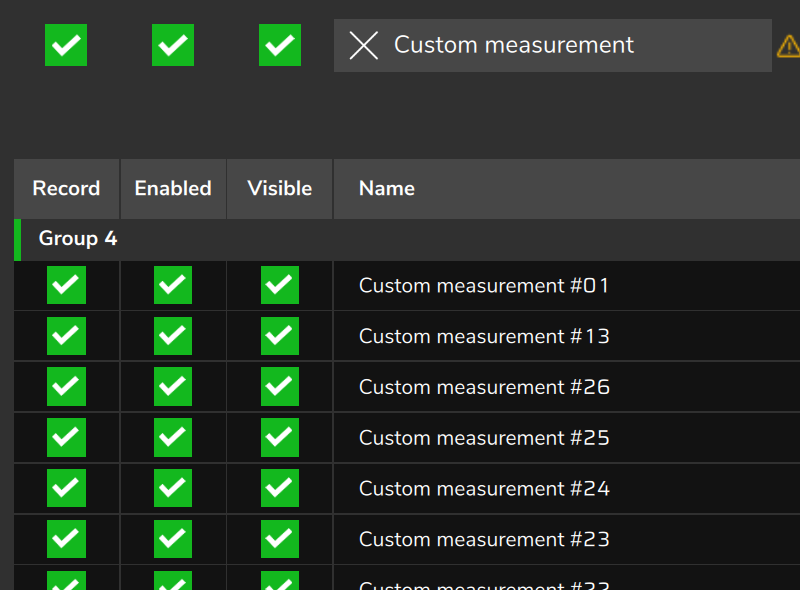
- Use one Value for VCU block for each intermediate value you will want to see in the log. The Custom measurement #01 to #36 are free to use and use no working memory (only 6 bytes of configuration).
- Do not write to a channel that has an owner, such as a physical input or a CAN channel: the owner can overwrite the value.
- Enable each channel in the datalogger (the VCU's log recorder, Datalogger settings screen) and confirm that it appears in the log. See the Output blocks chapter, Value for VCU sheet.
#Step 7: name every block
- The block name is the only comment the graph accepts. Open Block settings (the block's gear) and fill in Block name. Empty text is ignored: you cannot go back to the default name by erasing.
- Every field that goes to the user screen needs a Custom name. Without it the field appears with the default name, and two Fixed value blocks look the same to the customer. See the Building the graph and User screen chapters.
#Step 8: check the memory before writing to the VCU
- The editor's meter shows Memory: N%, the larger of RAM (working memory, 512-byte limit) and Settings (configuration memory, 2048-byte limit), adding up the enabled functions. The text turns amber above 75% and red above 90%, and the bar stops at 100% even if the actual use is higher.
- Confirm does not block anything. When writing, FuelTech Vision checks the limits and refuses to send with the Custom Functions memory exceeded box, which does not say which function or by how much. Use the meter beforehand.
The tables and the Average filter are the heaviest blocks: a Table 8x8 uses 330 bytes of configuration (16.1%) and the Average filter with 32 points uses 140 bytes of working memory (27.3%). Use the meter for the total.
#Step 9: test with the engine off
- The function runs whenever the VCU is on and the graph is loaded, even with the engine off. Ignition cuts and fuel cuts only act with RPM above 0, but the outputs, the ETC actions and the torque (EV) actions do act.
- Move the pedal and the throttle (TPS, the throttle position sensor) and read each log channel. The values the editor shows in the blocks are calculated by the PC, not read from the VCU, and the blocks with time (Delay, Cyclic timer, Ramp, Integrator, Derivative, Low pass filter) use the PC's clock: do not validate with them.
- If a pin is in manual test on the Outputs screen, the function does not command that pin.
#Step 10: validate in the log
- Record the input, the intermediate values and the result in the same recording. Compare each Custom measurement with what the drawing predicts and check the unit of each input.
- The editor does not warn you when the drawing has a feedback loop, that is, a link that goes back to an earlier block: the blocks in the loop and the ones that depend on them are left out of what the VCU runs. If a block does not act, look for a feedback loop.
- An output with no pin assigned stays silent and Value for VCU on a channel that does not accept writes does not record. Neither warns you. See the Troubleshooting and common errors chapter.
#Step 11: version the file
- Export saves a `.ftcf` file with the function's name (the default name is custom_function, and the function name can have up to 32 characters). Import erases the graph of the function that is open and loads the file in its place, without asking for confirmation and with no success or error message. The editor also has no Undo.
- For this reason, export before importing and save each change as a new file, with the version in the name (for example fan_v2.ftcf), instead of overwriting. See the Delivering to the customer chapter.