8. Buttons, navigation and cameras
The gauges in the Buttons category receive touch: the ECU Button sends a command to the VCU, the Navigation Button changes the dashboard screen and the Odometer/Hourmeter Reset Button resets the trip value. Those in the Cameras category show video. The SVG Button (7.3) does not receive touch. The buttons have the styles Classic, Cyberpunk, Modern and Neon, with the same behavior; the cameras, only Modern. Changing screens with a physical button is covered in 8.5.
#8.1 ECU Button
The ECU Button sends a command to the VCU; what the command does depends on the function that receives it (8.2).
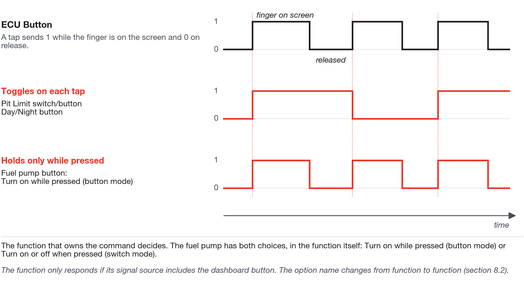
#How the touch works
On touch, the command goes to 1; on release, or when you slide your finger off the button, it goes back to 0. The button sends only this level: the function that receives the command decides whether it toggles, holds or follows the touch, and a function that holds works only while the finger is on the button. The button changes appearance at the moment of the touch and goes back to the real state after 1 second if the VCU does not confirm: if it changes and goes back, check the function's signal source (8.2).
#The commands in the list
The Command field (VCU Action section) opens the VCU Command window, with 59 of the 87 commands that the map format provides for; each one appears with the name of the button measurement. The most used: Engine Start/Stop button (and Engine Start button, Engine Stop button), Generic output #01 to #20, AC button, Pit Limit switch/button, Anti-Lag button, Day/Night button and Datalogger switch. There are also commands for traction control, progressive nitrous, fuel pump, interlock, burnout, consumption, gearbox position, lockup, EV charging and WMI, among others. The less common function names are explained in the glossary (section 16.1).
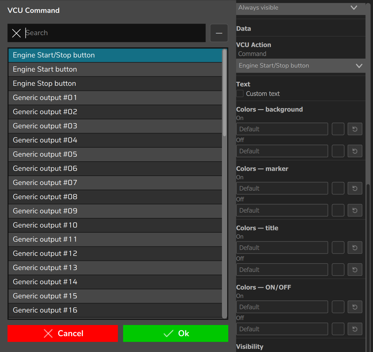
There are no commands for 2-Step, 3-Step, Transbrake, ProNitro, gear shift, map selection, bracket bump or throttle bump: firmware 00.03.00.54 has no function that reads those commands. ProNitro is not the same command as Progressive Nitrous #1 arm switch and Progressive Nitrous #2 arm switch, which are in the list. For the bracket, the list has only Bracket: Pre staging button, the command read by the Dash button option of the pre-staging output (section 8.2). To trigger the other functions, use a physical input or another signal source.
#ECU Button
Button that sends a command to the VCU and shows the state returned by the function.
- Command (VCU Action section): one of the 59 commands.
- Custom text (Text section): unchecked, it shows ON and OFF; checked, you write On (default ON) and Off (default OFF).
- Colors: four sections (background, marker, title and ON/OFF), each with On and Off. Simulation (editor): Force state and Status: On show the two appearances without the VCU.
- Visibility section: Show title comes unchecked (the title is Custom title, text ECU Button; the command name does not become the title); Show background and Show text ON/OFF come checked.
#8.2 Connecting the button to the function
The command has an effect only on the function that reads it, and only when that function's signal source includes the dashboard button: both sides must be connected. Exception: start (table below).
- On the dashboard, create the ECU Button and choose the Command.
- Open the screen of the function that should react (for example, Anti-lag or Pit limit), from its menu.
- In the signal source of that function, choose the option that connects the dashboard button; the name changes from function to function (table below).
- Write the map to the VCU (chapter 13).
- Test with the vehicle stopped and in a safe condition: the command really triggers the function.
| Function | Where to choose the dashboard button |
|---|---|
| Anti-lag | Activation list: Dashboard button |
| Day/Night | Day/night mode function: Dashboard mode |
| Pit limit, mechanical injection, progressive nitrous 1 and 2 | Mode or enable list: Dashboard |
| Start | No choice: with start enabled, firmware 00.03.00.54 always reads the dashboard button. External or Dashboard appears only on the phone, with no effect. |
| Bracket | Enable list of the pre-staging output: Dash button |
| Generic outputs, air conditioning, fuel pump and the rest | Function activation settings block, Signal source field: Dashboard button |
The Dashboard button option appears only for measurements that have a dashboard button command: if it does not appear, the command does not exist for the function. The datalogger needs no source.
#How each function reacts to touch
Verified in firmware 00.03.00.54:
- Toggles on every touch: air conditioning; pit limit and day/night (Dashboard mode); anti-lag (button or switch mode applies only to the external button); datalogger.
- You choose: on the fuel pump, Turn on while pressed (button mode) turns on while pressed and Turn on or off when pressed (switch mode) toggles; on the generic outputs, the Output activation mode field decides between Active the output by holding down (button mode) and Toggle ON/OFF when pressed (switch mode).
- Blip compensation: each touch advances one level and, after the last, goes back to the first. Idle (level): each touch adds one index.
For the other functions in the list, test on the bench whether the command toggles or follows the touch.
#8.3 Screen navigation button
The Navigation Button takes the dashboard to a chosen screen when pressed; releasing does nothing. Each button goes to one screen only: there is no next-screen or previous-screen button, so place on each screen the buttons that lead to the others.
#Navigation Button
Takes the dashboard to a chosen screen on touch.
- Screen index (Navigation section): default 0. It counts from 0: 0 is Screen 1, 1 is Screen 2, 2 is Screen 3, 3 is Screen 4. An index greater than or equal to the Number of screens is silently ignored: the touch does nothing and the app gives no warning. The field accepts any integer, so check the index of each button.
- Custom text (Text section): this button has no Show text ON/OFF and shows ON until you check Custom text and write the label in On and Off; for a readable label, write the screen name in On. Show title comes unchecked (initial title SCREEN); colors and Simulation (editor) are those of the ECU Button.
#8.4 Odometer/hourmeter reset button
The Odometer/Hourmeter Reset Button resets the odometer trip or the hour meter trip; the total is not reset.
The button resets on the first touch, without asking for confirmation, and the text CLEARED that appears afterward shows that the touch was made, not that the VCU confirmed it. If the dashboard runs on a screen that is touched while the vehicle is moving, put this button on a screen used while stopped.
#Odometer/Hourmeter Reset Button
Resets the chosen trip on touch.
- Function (Clear section): Odometer (default) or Hourmeter.
- Custom text: comes checked; On comes with CLEAR and Off with CLEARED. Colors, Show title (unchecked) and Simulation (editor) are those of the ECU Button.
When pressed, the button sends the command to reset the trip and shows CLEARED for 500 ms. The command has no response from the VCU. With no VCU or no connection, it shows NO CONNECTION for 1 second and sends nothing.
#8.5 Physical button to change screens
The FT700 and the FT700 Plus change screens with a physical button connected to a VCU input. Each time you press it, the dashboard advances one screen.
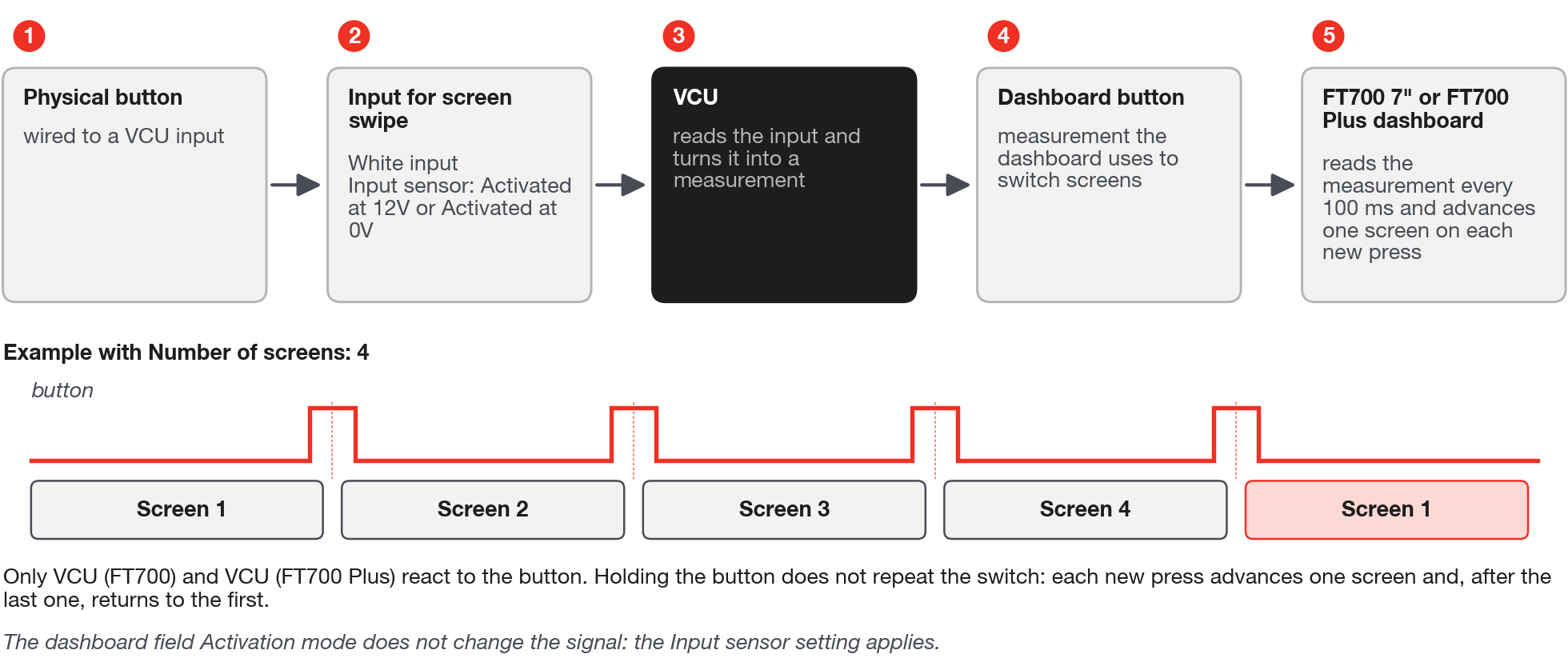
The input becomes the Dashboard button measurement. The running dashboard reads this measurement every 100 ms and, on each rising edge (from released to pressed), advances one screen; on the last one, it goes back to the first.
#Configure the input
- On the PC, open the dashboard editor and choose the target VCU (FT700) or VCU (FT700 Plus); on the other targets the screen-change input does not appear.
- In the Device tab, under General settings, use the button below Input for screen swipe. In the touch editors (section 4.3), open the Dashboard Settings modal, General tab; it closes and opens the VCU input screen.
- On the Signal source screen, choose White input, the physical white-wire input of the VCU harness. The other options are CAN (the CAN bus, the data network between modules), FTCAN2.0 (the FuelTech CAN protocol) and Switchpanel (the switch panel).
- Choose the physical input where the button is connected (same list as the Inputs screen).
- In Input sensor, choose the predefined sensor that describes the button: Activated at 12V, Activated at 12V with Pullup, Activated at 0V or Activated at 0V with Pullup (with Pullup, the input stays at a defined level while the button is released).
- Write the map to the VCU (chapter 13) and press the button with the dashboard open on the FT700: it should advance one screen with each press.
A very quick tap may not be seen, because the dashboard reads the button every 100 ms: press for a moment and check. Firmware 00.03.00.54 does not include the dashboard button among the measurements that a switch panel can write: use White input; if you choose Switchpanel, test before relying on it. Desktop, phone, tablet and the editor preview do not react to the physical button: on them, use the Navigation Button (8.3).
#8.6 Cameras
The dashboard shows video from an analog camera, connected to the VCU video input, and from an IP camera, by URL. The name and URL are not kept in the dashboard: they are in the map, on the Analog cameras and IP cameras screens, in the My VCU menu (PC and phone) or VCU (FT700 and FT700 Plus); the tablet menu does not have these screens. For this reason, exporting and importing a dashboard (chapter 13) does not carry the camera configuration: configure the cameras in the destination map. Both gauges use no measurement and choose Camera 1 or Camera 2 in the Camera field.
#IP Camera
Shows video from a network camera, using the URL configured in the map on the IP cameras screen, Name and URL fields of each camera.
The IP cameras screen has the Camera 1 - Activation mode field (Always enabled or Enable with Reverse gear, and the equivalent for camera 2), but the dashboard gauge does not apply this mode: it is always visible. To show it only in reverse, use Conditional visibility (7.5) with the gear measurement and reverse in the limits list, and check that the camera disappears in the other gears. For RTSP (video protocol used by IP cameras) on the PC, phone and tablet, test opening the video with the real camera.
#Analog Camera
Shows video from a camera connected to the VCU analog video input. The name comes from the Analog cameras screen, Name field (default Camera 1 and Camera 2). Only the FT700 7" and the FT700 Plus draw the video: on the PC, phone and tablet the gauge shows only the camera name. To show it only under a certain condition, use Conditional visibility (7.5).