9. Data, units and alerts
Every reading gauge shows one VCU measurement, such as engine speed, oil pressure or gear. This chapter covers choosing the measurement, the unit, the alert, the update rate and the dashboard with no data.
These do not read a measurement: Text, Image, shapes, buttons, cameras, Group, Map name, Analog clock and Date/Time.
#9.1 Choosing the data of a gauge
#Where the field is
A measurement is a value that the VCU calculates or reads from a sensor. You choose it in Data source, in the Data section of the properties panel. With Use custom title off, the title is the name of the measurement, in the language of the app. In the .ftds file the measurement is stored by number (DataSourceId), the one in the Number column of section 9.2.
Exceptions to the first field of the Data section:
- SVG Pointer, Pointer PNG, GIF and SVG Button: the field is under Data binding (in the SVG Button, it is called Data source (flag)).
- G Force: Data source (Lateral) and Data source (Longitudinal).
- Time selector: Bracket value.
- Shift: no field. It reads the RPM and the gear directly.
#The Choose item dialog
Tap or click Data source to open Choose item, look in Search (on the FT700, tap the field to open the keyboard; the search ignores case and accents) and confirm with Ok. Cancel closes without changing anything.
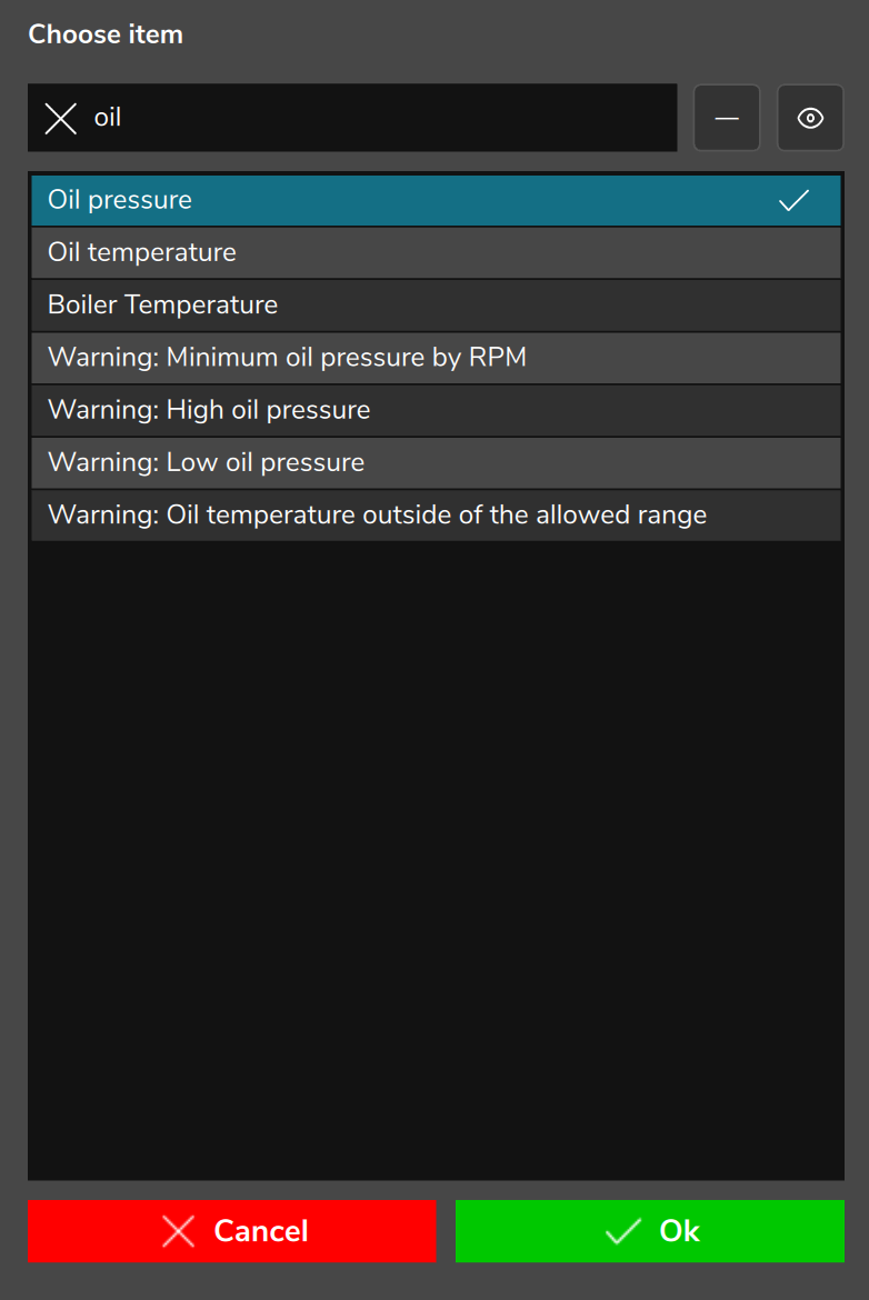
The list comes from the app catalog (about 1,180 measurements), not from the datalogger channels of the map. Appearing in it does not guarantee that the VCU measures that on your car: check the value with the VCU connected (section 9.6). There is no option to go back to None: you can only change it. Do not choose an item with no name.
Restricted lists: Speedometer, speed measurements only (10 items); SVG Button, on and off measurements only (381 items in this version); Time selector, only Bracket: Your dial, Bracket: Opponent dial and Bracket: Delay 1.
Old dashboards with Odometer may point to number 200, now vacant: the field appears empty and the gauge has no data. Choose Odometer (1108) or Trip odometer (1109) again.
#What the app stores when you choose the data
On the first choice, the app stores Minimum, Maximum and Decimals with the default values of the measurement (section 9.2), in the unit in use. A new Tachometer linked to Engine RPM gets a Maximum of 32000: adjust it to the car's engine.
When you change the measurement, the Reload data? dialog asks whether to reload minimum, maximum and decimal places with the defaults of the new measurement. Yes applies the defaults; No keeps the old values, without conversion. Low alert, High alert, Divisions and Divider never change: review them. When you switch to a measurement of another type, such as from pressure to temperature, No leaves the old scale: check Minimum and Maximum before writing.
On the G Force, only the horizontal axis receives the default range: check the vertical one.
#Measurements with text and the Data of Conditional visibility
In measurements with text, the alert and visibility limits become a text list. Gear: T, P, R, N, 1 to 16 and U. Gear selector: U, P, R, N, D, M, D1, D2, D3, D4 and S. On and off: OFF and ON.
In Conditional visibility, the Data field chooses the measurement that turns the gauge on and off, with the full list. It exists on the PC, on the FT700 7", on the FT700 Plus and on the phone. On the tablet the section does not exist: a dashboard with the condition already set works, but the tablet does not edit it. Modes: section 7.5.
#9.2 Table of the most used measurements
The number is what the .ftds stores. The default range is the one stored on the first choice (section 9.1), in the base unit (section 9.3), and the screen shows it converted. Rates: section 9.5. They apply to FuelTech Vision 3.00.54.
#Engine, temperatures and pressures
| Name on screen | Number | Default range | Rate per second |
|---|---|---|---|
| Engine RPM | 1 | 0 to 32000 RPM | 30 |
| MAP | 6 | -1 to 20 bar | 30 |
| Pedal pos. | 7 | 0 to 100 % | 30 |
| TPS | 8 | 0 to 100 % | 30 |
| Ignition timing | 17 | -64 to 100 ° | 30 |
| Injection time A | 10 | 0 to 32 ms | 30 |
| Battery voltage | 9 | 0 to 24 V | 10 |
| Engine temperature | 19 | -20 to 180 °C | 10 |
| Air temperature - intake | 18 | -20 to 180 °C | 10 |
| Oil temperature | 326 | -20 to 180 °C | 10 |
| Transmission temperature | 206 | 0 to 32000 °C | 10 |
| Oil pressure | 61 | 0 to 500 bar | 30 |
| Fuel pressure | 58 | 0 to 500 bar | 30 |
The default ranges of Oil pressure, Fuel pressure and Transmission temperature are too wide for a gauge: enter the Minimum and Maximum of your car's sensor.
#O2 sensor and vehicle
| Name on screen | Number | Default range | Rate per second |
|---|---|---|---|
| Closed Loop / VE Probe | 20 | 0 to 10 lambda | 30 |
| O2 target | 27 | 0 to 10 lambda | 30 |
| O2 closed loop correction | 29 | -100 to 100 % | 30 |
| O2 General | 322 | 0 to 10 lambda | 30 |
| VE closed loop - State | 1135 | 0 to 23 | 15 |
| Speed | 22 | 0 to 500 km/h | 30 |
| Gear | 69 | -3 to 16 | 30 |
| Gear selector | 455 | -1 to 9 | 10 |
| Gearbox position Park, Reverse, Neutral and Drive | 512 to 515 | 0 or 1 | 10 |
| Fuel Level Percentage | 199 | 0 to 100 % | 10 |
#Lights, alerts and counters
Light and alert measurements have the value 0 (off) or 1 (on). They serve as the Data of Conditional visibility and as the Data source (flag) of the SVG Button.
| Name on screen | Number | Default range | Rate per second |
|---|---|---|---|
| High beam | 267 | 0 or 1 | 10 |
| Low beam | 268 | 0 or 1 | 10 |
| Turn signal - Right | 272 | 0 or 1 | 10 |
| Turn signal - Left | 273 | 0 or 1 | 10 |
| 2-step activated | 564 | 0 or 1 | 30 |
| Night mode | 1001 | 0 or 1 | 30 |
| Warning: Over rev | 696 | 0 or 1 | 10 |
| Warning: Low oil pressure | 701 | 0 or 1 | 10 |
| Warning: Engine temperature | 703 | 0 or 1 | 10 |
| Odometer | 1108 | 0 to 1000000 km | 10 |
| Trip odometer | 1109 | 0 to 1000000 km | 10 |
- VCU alerts. There are 50 measurements, almost all with a name starting with "Warning:". Use them as the Data of a light.
- Custom measurements. Custom measurement #01 to #36 are numbers 456 to 491 and show the name given to the analog input in the map.
#9.3 Units
#The principle: the dashboard stores a fixed unit
Scale, alert limits, visibility limits and the values of pointers and GIFs are stored in the map and in the .ftds file in a fixed base unit for each type of measurement. The dashboard converts only when displaying and when typing: the same file works for maps with different units.
| Measurement type | Base unit | Measurement type | Base unit |
|---|---|---|---|
| Temperature | °C | Volume | L |
| Speed | km/h | Flow | L/min |
| Distance | km | Power | kW |
| Size | mm | Torque | Nm |
| Pressure | bar | Consumption | km/L |
| Tire pressure | psi | Injector flow | lb/h |
| Oxygen (O2 sensor) | lambda |
#Which unit the screen uses
| Where the dashboard runs | Units shown |
|---|---|
| FT700 and FT700 Plus (on the unit's display) | Always those of the map. |
| PC, phone and tablet | Those of the map or of the open log. With From Vision on, those of Vision, for all maps and logs. |
| Local dashboard, no map loaded | km/h, °C and bar (or those of Vision, with From Vision on); oxygen and flow in lambda and L/min. |
#Where to change the unit
- In the map: the Measurement units function, on four pages.
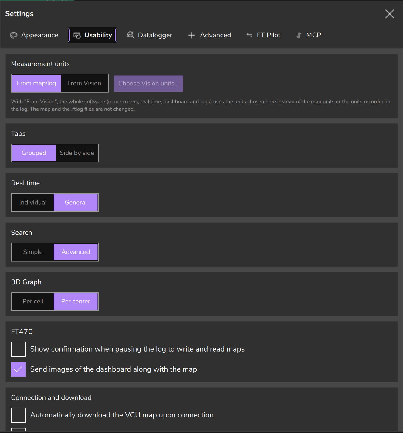
- On the PC: the Preferences button on the top bar (Settings window), Usability tab, Measurement units card. The switch toggles between From map/log and From Vision, which enables the Choose Vision units... button.
- On the phone and the tablet: the app Settings, Use the Vision units instead of the map/log units box, which enables the Choose Vision units button.
#Conversions used
| From / to | Calculation |
|---|---|
| °C to °F | x × 1.8 + 32 |
| km/h to mph | x ÷ 1.609344 |
| bar to psi | x × 14.5038 |
| bar to kPa | x × 100 |
| Lambda to AFR (air/fuel ratio by mass) | lambda × stoichiometric AFR of the map's fuel (or the value of the custom fuel) |
#What happens when you change the unit after building the dashboard
- Nothing is lost, the numbers change. Scale, alerts and Conditional visibility limits stay in the base unit and appear converted: they do not need to be redone.
- The round scale stops being round. A Speedometer of 0 to 300 km/h with 10 divisions becomes 0 to 186.4 mph, with whole-number labels. For round labels, type Minimum and Maximum again in the new unit and adjust Divisions.
- The O2 sensor reading in AFR depends on the map's fuel: changing it changes the numbers without touching the dashboard.
- Pointers and GIFs follow the unit. Value 1, Value 2, Initial value and Final value stay in the base unit. The angles do not change.
The Decimals are not converted: a pressure with 3 decimal places stays with 3 decimal places in psi. Choose the unit before adjusting the scale. If you change it later, review Minimum, Maximum, Divisions and Decimals.
#9.4 Gauge alerts
The alert changes the color of the number, the bar or the arc when the value passes a limit. It does not turn the gauge on or off: that is Conditional visibility.
#The fields
In the Alert section of the properties panel:
- Alert: the mode (table below).
- Low alert and High alert: the limits, which only appear with a mode other than Deactivated.
- Alerts bar: turns on the drawing of the alert zone on the scale (red marks and arcs). It exists on the Tachometer, the Speedometer and the Circular gauge.
#The five modes
| Mode | The alert turns on when |
|---|---|
| Deactivated | Never. |
| Intra | The value is inside the range between Low alert and High alert. |
| Extra | The value is outside the range: less than or equal to Low alert or greater than or equal to High alert. |
| Above | The value is greater than or equal to High alert. |
| Below | The value is less than or equal to Low alert. |
Digital Horizontal Modern: reads alert limits only between 0 and 100 (entry in section 6.5). For an RPM alert, temperature in °C or speed, use the Digital gauge or the Classic style of the Digital Horizontal, which leaves out only the limits of 0 or less.
#What each combination draws
G Force, SVG Pointer, Pointer PNG, GIF and Time selector do not have the Alert field. The table lists, by style, the gauges that react: 4 modes = the four modes; Above only = only the Above mode (the others do nothing and the Low alert is not read); Any = Above = any mode other than Deactivated acts as Above. A gauge not in the style's row draws no alert; neither do the Circular ideal value and the Electric gauge in any style.
| Style | 4 modes | Above only | Any = Above |
|---|---|---|---|
| Modern | Circular gauge, Horizontal bar, Vertical bar, Digital gauge, Digital Horizontal | RPM bar (the Tachometer: fixed zone, below) | None |
| Classic | Circular gauge (only the marks and arcs of the zone), Digital gauge, Digital Horizontal | RPM bar | None |
| Neon | Circular gauge, Ideal value, Horizontal bar, Vertical bar | None | Tachometer, Speedometer, RPM bar |
| Cyberpunk | Speedometer, Circular gauge, Ideal value, Horizontal bar, Vertical bar, Digital gauge, Digital Horizontal | RPM bar | None |
On the Modern Tachometer, the Above mode marks a fixed zone of the scale, from the High alert to the end: the labels turn red (and the marks, with Alerts bar), like the red zone of a tachometer. For a warning that reacts to engine speed, use the RPM bar with the Above mode or the Shift.
The alert does not blink and the color is fixed, with no field to change it: red (in Classic, dark red and a red lamp in an image). For a warning light that appears and disappears according to the measurement, use Conditional visibility (section 7.5).
#Shift: the alert is the shift point
On the Shift, the High alert field is the shift point, in RPM, with no unit conversion. The drawing does not read the mode: the light turns on when the RPM reaches the shift point, even with Deactivated. The field only appears with a mode other than Deactivated, and a new Shift starts with the shift point at 0, lit all the time. How to type it: the Shift entry (section 6.5).
#Building an alert that works
- Choose the Data source (section 9.1) and set Minimum and Maximum to the real range of the sensor.
- Check in the table whether the gauge and the style draw the mode you want.
- Choose the mode and type the limits in the unit the screen shows, within the scale (on the Circular gauge, the bars and the Ideal value, a limit equal to the Minimum or the Maximum does not count). They start at 0 (the High alert of the Vertical bar, at 100): on the Digital gauge and the Circular gauge, Above with High alert at 0 turns the alert on with any value from 0 up.
- Connect the VCU and check the alert with the real value.
#9.5 Update rate by measurement
The gauge follows the rate of the measurement it reads. Each measurement has one of three rates, and section 9.2 gives the rate of each measurement listed.
| Rate | Interval | Examples |
|---|---|---|
| 30 per second | 33 ms | Engine RPM, MAP, TPS, Speed, Oil pressure, Fuel pressure, O2 sensors |
| 15 per second | 67 ms | VE closed loop - State |
| 10 per second | 100 ms | Temperatures, Battery voltage, fuel level, odometer, headlights, turn signals, VCU alerts |
- Conditional visibility is evaluated at the rate of the measurement in the Data field, not at the rate of the gauge's measurement.
- A gauge with no Data source is updated 10 times per second. The Shift reads the RPM at 10 per second, not at 30.
For an engine speed warning at 30 per second, use the Above alert of an RPM bar linked to Engine RPM, in a style that draws that alert (table in section 9.4).
The table gives the redraw rate of the app, not how many values per second the VCU sends.
#FT470 and the request for measurements
With the FT470, the app asks the unit for: a base set (RPM, speed, gear, MAP, TPS, battery voltage, engine and air temperatures, screen change button, day/night button, active map, vehicle state, engine sync and start) plus the Data source measurements of the gauges on the open screen. A measurement used only as the Data of Conditional visibility is not included in the request: if a warning light does not react, check whether the measurement is in the base set or is also the Data source of some gauge on the same screen. What to edit for the FT470: section 11.6.
#9.6 What the gauge shows with no data
#The initial value
When the app opens, the measurements start with an initial value, before the VCU sends anything: almost all are 0; the O2 sensor (lambda) is 1; the on and off ones are off. The Digital gauge shows "---" with no Data source.
The editor has no value simulator: without the VCU, the gauges start from the initial value and may differ from the car.
#Situation by situation
| Situation | What the dashboard shows | What to do |
|---|---|---|
| Connected, but the VCU does not send the measurement | The last value received; if none ever arrived, the initial one. | Check the measurement with the VCU connected and the sensor on. |
| Missing or faulty sensor | The value the VCU sends, which can vary by measurement. The gauge has no signal of its own for a disconnected or shorted sensor. | Test on the bench with the sensor disconnected and note what the dashboard shows. |
| Connection lost | The RPM goes to 0 and the dashboard buttons go back to the initial state. The other measurements stay frozen at the last value. | With the RPM at 0 and the rest frozen, check the connection before concluding that the engine stopped. |
#Lights with Conditional visibility and Shift with no data
With no measurement in Data, the condition is always true and the gauge is visible. With a measurement and no data, the value is 0 (the O2 sensor, 1) and the result depends on the mode and the limits (table in section 7.5). For a lambda light, use 1 in place of 0 and check in the chosen unit, which may be AFR.
With no data, and after the connection drops, the RPM of the Shift is 0: lit with the shift point at 0, off above 0.
#Check before taking the dashboard to the car
- Each reading gauge has Data source filled in.
- Minimum and Maximum match the car's sensor, not the default range of the measurement.
- The unit is the one you expect (section 9.3) and each alert uses a mode that the gauge and the style draw (section 9.4).
- Each light with Conditional visibility has both limits typed in (section 7.5), and the Shift has the shift RPM.
- Each ECU Button has the Command you want (section 8.1).
- With the VCU connected and the engine running, each measurement shows a consistent value, and the alerts and lights change when they should.
The list of what to check before writing is in section 3.3.